| Intro | Cap Reactance Formula | Volt dist Series Caps | Cap Volt Divider |
| Example 1 | Example 2 |
Capacitive Voltage Divider
|
| Capacitive Voltage Divider Voltage divider circuits may be constructed from reactive components just as easily as they may be constructed from fixed value resistors |
| A capacitor opposes current flow just like a resistor, but unlike a resistor which dissipates its unwanted energy in the form of heat, a capacitor stores energy on its plates when it charges and releases or gives back the energy into the connected circuit when it discharges. |
|
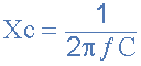 capacitive reactance formula
Where:
Xc = Capacitive Reactance in Ohms, (Ω)
π (pi) = a numeric constant of 3.142
ƒ = Frequency in Hertz, (Hz)
C = Capacitance in Farads, (F)
capacitive reactance formula
Where:
Xc = Capacitive Reactance in Ohms, (Ω)
π (pi) = a numeric constant of 3.142
ƒ = Frequency in Hertz, (Hz)
C = Capacitance in Farads, (F)

|
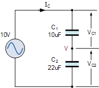
capacitive voltage divider
Consider the two capacitors, C1 and C2 connected in series across an alternating supply of 10 volts. As the two capacitors are in series, the charge Q on them is the same, but the voltage across them will be different and related to their capacitance values, as V = Q/C. |
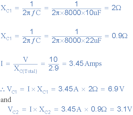
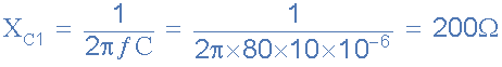 capacitive reactance of 10uF
Capacitive Reactance of 22uF capacitor
capacitive reactance of 10uF
Capacitive Reactance of 22uF capacitor
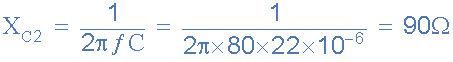 capacitive reactance of 22uF
Total capacitive reactance of series circuit – Note that reactance’s in
series are added together just like resistors in series.
capacitive reactance of 22uF
Total capacitive reactance of series circuit – Note that reactance’s in
series are added together just like resistors in series.
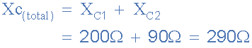 capacitive reactance of circuit
or:
capacitive reactance of circuit
or:
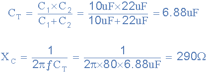 total capacitive reactance
Circuit current
total capacitive reactance
Circuit current
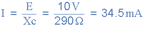 circuit current
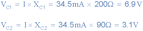
Then the voltage drop across each capacitor in series capacitive voltage
divider will be:
circuit current
Then the voltage drop across each capacitor in series capacitive voltage
divider will be:
 capacitive divider voltage drop
When the capacitor values are different, the smaller value capacitor will
charge itself to a higher voltage than the larger value capacitor, and in
our example above this was 6.9 and 3.1 volts respectively. Since
Kirchhoff’s voltage law applies to this and every series connected
circuit, the total sum of the individual voltage drops will be equal in
value to the supply voltage, VS and 6.9 + 3.1 does indeed equal 10 volts.
Note that the ratios of the voltage drops across the two capacitors
connected in a series capacitive voltage divider circuit will always remain
the same regardless of the supply frequency. Then the two voltage drops of
6.9 volts and 3.1 volts above in our simple example will remain the same
even if the supply frequency is increased from 80Hz to 8000Hz as shown.
capacitive divider voltage drop
When the capacitor values are different, the smaller value capacitor will
charge itself to a higher voltage than the larger value capacitor, and in
our example above this was 6.9 and 3.1 volts respectively. Since
Kirchhoff’s voltage law applies to this and every series connected
circuit, the total sum of the individual voltage drops will be equal in
value to the supply voltage, VS and 6.9 + 3.1 does indeed equal 10 volts.
Note that the ratios of the voltage drops across the two capacitors
connected in a series capacitive voltage divider circuit will always remain
the same regardless of the supply frequency. Then the two voltage drops of
6.9 volts and 3.1 volts above in our simple example will remain the same
even if the supply frequency is increased from 80Hz to 8000Hz as shown.
 capacitive voltage divider drop
While the voltage ratios across the two capacitors may stay the same, as the
supply frequency increases, the combined capacitive reactance decreases, and
therefore so too does the total circuit impedance. This reduction in
impedance causes more current to flow. For example, at 80Hz we calculated
the circuit current above to be about 34.5mA, but at 8kHz, the supply
current increased to 3.45A, 100 times more. Therefore, the current flowing
through a capacitive voltage divider is proportional to frequency or I ∝
ƒ.
We have seen here that a capacitor divider is a network of series connected
capacitors, each having a AC voltage drop across it. As capacitive voltage
dividers use the capacitive reactance value of a capacitor to determine the
actual voltage drop, they can only be used on frequency driven supplies and
as such do not work as DC voltage dividers. This is mainly due to the fact
that capacitors block DC and therefore no current flows.
Capacitive voltage divider circuits are used in a variety of electronics
applications ranging from Colpitts Oscillators, to capacitive touch
sensitive screens that change their output voltage when touched by a persons
finger, to being used as a cheap substitute for mains transformers in
dropping high voltages such as in mains connected circuits that use low
voltage electronics or IC’s etc.
Because as we now know, the reactance of both capacitors changes with
frequency (at the same rate), so the voltage division across a capacitive
voltage divider circuit will always remain the same keeping a steady voltage
divider.
capacitive voltage divider drop
While the voltage ratios across the two capacitors may stay the same, as the
supply frequency increases, the combined capacitive reactance decreases, and
therefore so too does the total circuit impedance. This reduction in
impedance causes more current to flow. For example, at 80Hz we calculated
the circuit current above to be about 34.5mA, but at 8kHz, the supply
current increased to 3.45A, 100 times more. Therefore, the current flowing
through a capacitive voltage divider is proportional to frequency or I ∝
ƒ.
We have seen here that a capacitor divider is a network of series connected
capacitors, each having a AC voltage drop across it. As capacitive voltage
dividers use the capacitive reactance value of a capacitor to determine the
actual voltage drop, they can only be used on frequency driven supplies and
as such do not work as DC voltage dividers. This is mainly due to the fact
that capacitors block DC and therefore no current flows.
Capacitive voltage divider circuits are used in a variety of electronics
applications ranging from Colpitts Oscillators, to capacitive touch
sensitive screens that change their output voltage when touched by a persons
finger, to being used as a cheap substitute for mains transformers in
dropping high voltages such as in mains connected circuits that use low
voltage electronics or IC’s etc.
Because as we now know, the reactance of both capacitors changes with
frequency (at the same rate), so the voltage division across a capacitive
voltage divider circuit will always remain the same keeping a steady voltage
divider.