
Ultracapacitors are electrical energy storage devices that have the ability to store a large amount of electrical charge
| Intro | Charge On a Cap | Construction | Increasing Ultracaps Val |
| Example 1 | 6x2 Ucap Array | Ultracap Energy | Summary |
Ultracapacitors
|
|
Ultracapacitors
Ultracapacitors are electrical energy storage devices that have the ability to store a large amount of electrical charge |
A capacitor has a constant of proportionality, called capacitance, symbol C, which represents the capacitor’s ability or capacity to store an electrical charge with the amount of charge depending on a capacitor capacitance value as: Q ∞ C. |
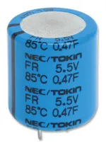
A Typical Ultracapacitor |
 capacitance and charge on a capacitor
Where: Q (Charge, in Coulombs) = C (Capacitance, in Farads) times V
(Voltage, in Volts)
The unit of capacitance is the coulomb/volt, which is also called the Farad
(F) [named after M. Faraday] with one farad being defined as the capacitance
of a capacitor, which requires a charge of 1 coulomb to establish a
potential difference of 1 volt between its two plates.
But a conventional one farad capacitor would be very large for most
practical electronic applications, hence much smaller units like the
microfarad (μF), nanofarad (nF) and picofarad (pF) are commonly used
where:
Microfarad (μF) 1μF = 1/1,000,000 = 0.000001 = 10-6 F
Nanofarad (nF) 1nF = 1/1,000,000,000 = 0.000000001 = 10-9 F
Picofarad (pF) 1pF = 1/1,000,000,000,000 = 0.000000000001 = 10-12 F
However, there is another type of capacitor available, called an
Ultracapacitor or Supercapacitor which can provide values from a few milli
-farads (mF) to ten’s of farads of capacitance in a very small size
allowing for much more electrical energy to be stored between their plates.
In our tutorial about Capacitance and Charge we saw that the energy stored
in a capacitor is given by the equation:
capacitance and charge on a capacitor
Where: Q (Charge, in Coulombs) = C (Capacitance, in Farads) times V
(Voltage, in Volts)
The unit of capacitance is the coulomb/volt, which is also called the Farad
(F) [named after M. Faraday] with one farad being defined as the capacitance
of a capacitor, which requires a charge of 1 coulomb to establish a
potential difference of 1 volt between its two plates.
But a conventional one farad capacitor would be very large for most
practical electronic applications, hence much smaller units like the
microfarad (μF), nanofarad (nF) and picofarad (pF) are commonly used
where:
Microfarad (μF) 1μF = 1/1,000,000 = 0.000001 = 10-6 F
Nanofarad (nF) 1nF = 1/1,000,000,000 = 0.000000001 = 10-9 F
Picofarad (pF) 1pF = 1/1,000,000,000,000 = 0.000000000001 = 10-12 F
However, there is another type of capacitor available, called an
Ultracapacitor or Supercapacitor which can provide values from a few milli
-farads (mF) to ten’s of farads of capacitance in a very small size
allowing for much more electrical energy to be stored between their plates.
In our tutorial about Capacitance and Charge we saw that the energy stored
in a capacitor is given by the equation:
 energy stored in a capacitor
Where: E is the energy stored in the electric field in joules, V is the
potential difference across the plates and C is the capacitance of the
capacitor in farads and defined as:
energy stored in a capacitor
Where: E is the energy stored in the electric field in joules, V is the
potential difference across the plates and C is the capacitance of the
capacitor in farads and defined as:
 capacitance of a capacitor
Where: ε is the permittivity of the material between the plates, A is the
area of the plates, and d is the separation of the plates.
Ultracapacitors are another type of capacitor which is constructed to have a
large conductive plate, called an electrode, surface area (A) as well as a
very small distance (d) between them. Unlike conventional capacitors that
use a solid and dry dielectric material such as Teflon, Polyethylene, Paper,
etc, the ultracapacitor uses a liquid or wet electrolyte between its
electrodes making it more of an electrochemical device similar to an
electrolytic capacitor.
Although an ultracapacitor is a type of electrochemical device, no chemical
reactions are involved in the storing of its electrical energy. This means
that the ultra-capacitor remains effectively an electrostatic device storing
its electrical energy in the form of an electric field between its two
conducting electrodes as shown.
capacitance of a capacitor
Where: ε is the permittivity of the material between the plates, A is the
area of the plates, and d is the separation of the plates.
Ultracapacitors are another type of capacitor which is constructed to have a
large conductive plate, called an electrode, surface area (A) as well as a
very small distance (d) between them. Unlike conventional capacitors that
use a solid and dry dielectric material such as Teflon, Polyethylene, Paper,
etc, the ultracapacitor uses a liquid or wet electrolyte between its
electrodes making it more of an electrochemical device similar to an
electrolytic capacitor.
Although an ultracapacitor is a type of electrochemical device, no chemical
reactions are involved in the storing of its electrical energy. This means
that the ultra-capacitor remains effectively an electrostatic device storing
its electrical energy in the form of an electric field between its two
conducting electrodes as shown.
 ultracapacitor construction
The double sided coated electrodes are made from graphite carbon in the form
of activated conductive carbon, carbon nanotubes or carbon gels. A porous
paper membrane called a separator keeps the electrodes apart but allows
positive ion to pass through while blocking the larger electrons. Both the
paper separator and carbon electrodes are impregnated with the liquid
electrolyte with an aluminium foil used in between the two to act as the
current collector making electrical connection to the ultracapacitors solder
tabs.
The double layer construction of the carbon electrodes and separator may be
very thin but their effective surface area into the thousands of meters
squared when coiled up together. Then in order to increase the capacitance
of an ultra-capacitor, it is obvious that we need to increase the contact
surface area, A (in m2) without increasing the capacitors physical size, or
use a special type of electrolyte to increase the available positive ions to
increase conductivity.
Then ultra-capacitors make excellent energy storage devices because of their
high values of capacitance up into the hundreds of farads, due to the very
small distance d or separation of their plates and the electrodes high
surface area A for the formation on the surface of a layer of electrolytic
ions forming a double layer. This construction effectively creates two
capacitors, one at each carbon electrode, giving the ultracapacitor the
secondary name of “double layer capacitor” forming two capacitors in
series.
However, the problem with this small size is that the voltage across the
capacitor can only be very low as the rated voltage of the ultra-capacitor
cell is determined mainly by the decomposition voltage of the electrolyte.
Then a typical capacitor cell has a working voltage of between 1 to 3 volts,
depending on the electrolyte used, which can limit the amount of electrical
energy it can store.
In order to store charge at a reasonable voltage ultracapacitors have to be
connected in series. Unlike electrolytic and electrostatic capacitors, ultra
-capacitors are characterized by there low terminal voltage. In order to
increase there rated terminal voltage to tens of volts, ultracapacitor cells
must be connected in series, or in parallel to achieve higher capacitance
values as shown.
ultracapacitor construction
The double sided coated electrodes are made from graphite carbon in the form
of activated conductive carbon, carbon nanotubes or carbon gels. A porous
paper membrane called a separator keeps the electrodes apart but allows
positive ion to pass through while blocking the larger electrons. Both the
paper separator and carbon electrodes are impregnated with the liquid
electrolyte with an aluminium foil used in between the two to act as the
current collector making electrical connection to the ultracapacitors solder
tabs.
The double layer construction of the carbon electrodes and separator may be
very thin but their effective surface area into the thousands of meters
squared when coiled up together. Then in order to increase the capacitance
of an ultra-capacitor, it is obvious that we need to increase the contact
surface area, A (in m2) without increasing the capacitors physical size, or
use a special type of electrolyte to increase the available positive ions to
increase conductivity.
Then ultra-capacitors make excellent energy storage devices because of their
high values of capacitance up into the hundreds of farads, due to the very
small distance d or separation of their plates and the electrodes high
surface area A for the formation on the surface of a layer of electrolytic
ions forming a double layer. This construction effectively creates two
capacitors, one at each carbon electrode, giving the ultracapacitor the
secondary name of “double layer capacitor” forming two capacitors in
series.
However, the problem with this small size is that the voltage across the
capacitor can only be very low as the rated voltage of the ultra-capacitor
cell is determined mainly by the decomposition voltage of the electrolyte.
Then a typical capacitor cell has a working voltage of between 1 to 3 volts,
depending on the electrolyte used, which can limit the amount of electrical
energy it can store.
In order to store charge at a reasonable voltage ultracapacitors have to be
connected in series. Unlike electrolytic and electrostatic capacitors, ultra
-capacitors are characterized by there low terminal voltage. In order to
increase there rated terminal voltage to tens of volts, ultracapacitor cells
must be connected in series, or in parallel to achieve higher capacitance
values as shown.
 increasing an ultracapacitors value
Where: VCELL is the voltage of one cell, and CCELL is the capacitance of one
cell.
As the voltage of each capacitor cell is about 3.0 volts, connecting more
capacitor cells together in series will increase the voltage. While
connecting more capacitor cells in parallel will increase its capacitance.
Then we can define the total voltage and total capacitance of a
ultracapacitor bank as:
increasing an ultracapacitors value
Where: VCELL is the voltage of one cell, and CCELL is the capacitance of one
cell.
As the voltage of each capacitor cell is about 3.0 volts, connecting more
capacitor cells together in series will increase the voltage. While
connecting more capacitor cells in parallel will increase its capacitance.
Then we can define the total voltage and total capacitance of a
ultracapacitor bank as:
 ultracapacitors voltage and capacitance value
Where: M is the number of columns and N is the number of rows. Note also
that like batteries, ultracapacitor and supercapacitors have a defined
polarity with the positive terminal marked on the capacitor body.
ultracapacitors voltage and capacitance value
Where: M is the number of columns and N is the number of rows. Note also
that like batteries, ultracapacitor and supercapacitors have a defined
polarity with the positive terminal marked on the capacitor body.
 ultracapacitors voltage
The array will therefore have two capacitor cells of 2.75v each connected in
series to provide the required 5.5v.
ultracapacitors voltage
The array will therefore have two capacitor cells of 2.75v each connected in
series to provide the required 5.5v.
 ultracapacitors capacitance
Then the array will have a total of six individual columns, consisting of
two rows of six thereby forming an ultracapacitor with a 6 x 2 array as
shown.
ultracapacitors capacitance
Then the array will have a total of six individual columns, consisting of
two rows of six thereby forming an ultracapacitor with a 6 x 2 array as
shown.
 ultracapacitors array
 energy stored in ultracapacitors
Where: E is the energy stored in joules. Then for our ultracapacitor example
above, the amount of energy stored by the array is given as:
energy stored in ultracapacitors
Where: E is the energy stored in joules. Then for our ultracapacitor example
above, the amount of energy stored by the array is given as:
 electrical energy stored our ultracapacitors
Then the maximum amount of energy that can be stored by our ultracapacitor
is 22.7 joules, which was originally supplied by the 5.5 volt charging
supply. This stored energy remains available as charge in the electrolyte
dielectric and when connected to a load, the ultracapacitors entire 22.69
joules of energy is made available as an electric current. Obviously, when
the ultracapacitor is fully discharged, the stored energy is zero.
Then we can see that an ideal ultracapacitor would not consume or dissipate
energy, but instead take power from an external charging circuit to store
energy in its electrolyte field and then return this stored energy when
delivering power to a load.
In our simple example above, the energy stored by the ultracapacitor was
about 23 joules, but with large capacitance values and higher voltage
ratings, the energy density of ultracapacitors can be very large making them
ideal as energy storage devices.
In fact, ultracapacitors with ratings into the thousands of farads and
hundreds of volts are now being used in hybrid electric vehicles (including
Formula 1) as solid state energy storage devices for regenerative braking
systems as they can quickly giving out and receiving energy during braking
and accelerating afterwards. Ultra and super-capacitors are also used in
renewable energy systems to replace lead acid batteries.
electrical energy stored our ultracapacitors
Then the maximum amount of energy that can be stored by our ultracapacitor
is 22.7 joules, which was originally supplied by the 5.5 volt charging
supply. This stored energy remains available as charge in the electrolyte
dielectric and when connected to a load, the ultracapacitors entire 22.69
joules of energy is made available as an electric current. Obviously, when
the ultracapacitor is fully discharged, the stored energy is zero.
Then we can see that an ideal ultracapacitor would not consume or dissipate
energy, but instead take power from an external charging circuit to store
energy in its electrolyte field and then return this stored energy when
delivering power to a load.
In our simple example above, the energy stored by the ultracapacitor was
about 23 joules, but with large capacitance values and higher voltage
ratings, the energy density of ultracapacitors can be very large making them
ideal as energy storage devices.
In fact, ultracapacitors with ratings into the thousands of farads and
hundreds of volts are now being used in hybrid electric vehicles (including
Formula 1) as solid state energy storage devices for regenerative braking
systems as they can quickly giving out and receiving energy during braking
and accelerating afterwards. Ultra and super-capacitors are also used in
renewable energy systems to replace lead acid batteries.