| Intro | Capacitor Capacitance | Standard Capacitance Units | Caps Capacitance |
| Example 1 | Dielectric | Complex Permittivity | Multi Plate Capacitor |
| Voltage Rating | Summary | ||
Introduction to Capacitors
|
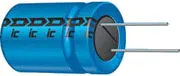
| Introduction to Capacitors Capacitors are simple passive device that can store an electrical charge on their plates when connected to a voltage source |
| Due to this insulating layer, DC current can not flow through the capacitor as it blocks it allowing instead a voltage to be present across the plates in the form of an electrical charge. The conductive metal plates of a capacitor can be either square, circular or rectangular, or they can be of a cylindrical general shape, size and construction of a parallel plate capacitor depending on its application and voltage rating. | 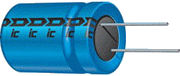
A Typical Capacitor |
 introduction to capacitors the symbol
The parallel plate capacitor is the simplest form of capacitor. It can be
constructed using two metal or metallised foil plates at a distance parallel
to each other, with its capacitance value in Farads, being fixed by the
surface area of the conductive plates and the distance of separation between
them. Altering any two of these values alters the the value of its
capacitance and this forms the basis of operation of the variable
capacitors.
Also, because capacitors store the energy of the electrons in the form of an
electrical charge on the plates the larger the plates and/or smaller their
separation the greater will be the charge that the capacitor holds for any
given voltage across its plates. In other words, larger plates, smaller
distance, more capacitance.
By applying a voltage to a capacitor and measuring the charge on the plates,
the ratio of the charge Q to the voltage V will give the capacitance value
of the capacitor and is therefore given as: C = Q/V this equation can also
be re-arranged to give the familiar formula for the quantity of charge on
the plates as: Q = C x V
Although we have said that the charge is stored on the plates of a
capacitor, it is more exact to say that the energy within the charge is
stored in an “electrostatic field” between the two plates. When an
electric current flows into the capacitor, it charges up, so the
electrostatic field becomes much stronger as it stores more energy between
the plates.
Likewise, as the current flowing out of the capacitor, discharging it, the
potential difference between the two plates decreases and the electrostatic
field decreases as the energy moves out of the plates.
The property of a capacitor to store charge on its plates in the form of an
electrostatic field is called the Capacitance of the capacitor. Not only
that, but capacitance is also the property of a capacitor which resists the
change of voltage across it.
introduction to capacitors the symbol
The parallel plate capacitor is the simplest form of capacitor. It can be
constructed using two metal or metallised foil plates at a distance parallel
to each other, with its capacitance value in Farads, being fixed by the
surface area of the conductive plates and the distance of separation between
them. Altering any two of these values alters the the value of its
capacitance and this forms the basis of operation of the variable
capacitors.
Also, because capacitors store the energy of the electrons in the form of an
electrical charge on the plates the larger the plates and/or smaller their
separation the greater will be the charge that the capacitor holds for any
given voltage across its plates. In other words, larger plates, smaller
distance, more capacitance.
By applying a voltage to a capacitor and measuring the charge on the plates,
the ratio of the charge Q to the voltage V will give the capacitance value
of the capacitor and is therefore given as: C = Q/V this equation can also
be re-arranged to give the familiar formula for the quantity of charge on
the plates as: Q = C x V
Although we have said that the charge is stored on the plates of a
capacitor, it is more exact to say that the energy within the charge is
stored in an “electrostatic field” between the two plates. When an
electric current flows into the capacitor, it charges up, so the
electrostatic field becomes much stronger as it stores more energy between
the plates.
Likewise, as the current flowing out of the capacitor, discharging it, the
potential difference between the two plates decreases and the electrostatic
field decreases as the energy moves out of the plates.
The property of a capacitor to store charge on its plates in the form of an
electrostatic field is called the Capacitance of the capacitor. Not only
that, but capacitance is also the property of a capacitor which resists the
change of voltage across it.
| Microfarad | 1(μF) | 1μF = 1/1,000,000 = 0.000001 = 10-6 F |
| Nanofarad | (nF) | 1nF = 1/1,000,000,000 = 0.000000001 = 10-9 F |
| Picofarad | (pF) | 1pF = 1/1,000,000,000,000 = 0.000000000001 = 10-12 F |
| Pico-Farad (pF) | Nano-Farad (nF) | Micro-Farad (μF) | Farads (F) |
|---|---|---|---|
| 1.0 | 0.001 | ||
| 10.0 | 0.01 | ||
| 1,000,000 | 1,000 | 1.0 | |
| 10,000 | 10.0 | ||
| 100,000 | 100 | ||
| 1,000,000 | 1,000 | 0.001 | |
| 10,000 | 0.01 | ||
| 100,000 | 0.1 | ||
| 1,000,000 | 1.0 |
 the capacitance of a capacitor
Then the value of the capacitor consisting of two plates separated by air is
calculated as 0.221nF, or 221pF.
the capacitance of a capacitor
Then the value of the capacitor consisting of two plates separated by air is
calculated as 0.221nF, or 221pF.
 In other words, if we take the permittivity of free space, εo as our base
level and make it equal to one, when the vacuum of free space is replaced by
some other type of insulating material, their permittivity of its dielectric
is referenced to the base dielectric of free space giving a multiplication
factor known as “relative permittivity”, εr. So the value of the
complex permittivity, ε will always be equal to the relative permittivity
times one.
Typical units of dielectric permittivity, ε or dielectric constant for
common materials are: Pure Vacuum = 1.0000, Air = 1.0006, Paper = 2.5 to
3.5, Glass = 3 to 10, Mica = 5 to 7, Wood = 3 to 8 and Metal Oxide Powders =
6 to 20 etc. This then gives us a final equation for the capacitance of a
capacitor as:
In other words, if we take the permittivity of free space, εo as our base
level and make it equal to one, when the vacuum of free space is replaced by
some other type of insulating material, their permittivity of its dielectric
is referenced to the base dielectric of free space giving a multiplication
factor known as “relative permittivity”, εr. So the value of the
complex permittivity, ε will always be equal to the relative permittivity
times one.
Typical units of dielectric permittivity, ε or dielectric constant for
common materials are: Pure Vacuum = 1.0000, Air = 1.0006, Paper = 2.5 to
3.5, Glass = 3 to 10, Mica = 5 to 7, Wood = 3 to 8 and Metal Oxide Powders =
6 to 20 etc. This then gives us a final equation for the capacitance of a
capacitor as:
 capacitance of a capacitor
One method used to increase the overall capacitance of a capacitor while
keeping its size small is to “interleave” more plates together within a
single capacitor body. Instead of just one set of parallel plates, a
capacitor can have many individual plates connected together thereby
increasing the surface area, A of the plates.
For a standard parallel plate capacitor as shown above, the capacitor has
two plates, labelled A and B. Therefore as the number of capacitor plates is
two, we can say that n = 2, where “n” represents the number of plates.
Then our equation above for a single parallel plate capacitor should really
be:
capacitance of a capacitor
One method used to increase the overall capacitance of a capacitor while
keeping its size small is to “interleave” more plates together within a
single capacitor body. Instead of just one set of parallel plates, a
capacitor can have many individual plates connected together thereby
increasing the surface area, A of the plates.
For a standard parallel plate capacitor as shown above, the capacitor has
two plates, labelled A and B. Therefore as the number of capacitor plates is
two, we can say that n = 2, where “n” represents the number of plates.
Then our equation above for a single parallel plate capacitor should really
be:
 actual capacitance of a capacitor
However, the capacitor may have two parallel plates but only one side of
each plate is in contact with the dielectric in the middle as the other side
of each plate forms the outside of the capacitor. If we take the two halves
of the plates and join them together we effectively only have “one”
whole plate in contact with the dielectric.
As for a single parallel plate capacitor, n – 1 = 2 – 1 which equals 1
as C = (εo*εr x 1 x A)/d is exactly the same as saying: C = (εo*εr*A)/d
which is the standard equation above.
Now suppose we have a capacitor made up of 9 interleaved plates, then n = 9
as shown.
actual capacitance of a capacitor
However, the capacitor may have two parallel plates but only one side of
each plate is in contact with the dielectric in the middle as the other side
of each plate forms the outside of the capacitor. If we take the two halves
of the plates and join them together we effectively only have “one”
whole plate in contact with the dielectric.
As for a single parallel plate capacitor, n – 1 = 2 – 1 which equals 1
as C = (εo*εr x 1 x A)/d is exactly the same as saying: C = (εo*εr*A)/d
which is the standard equation above.
Now suppose we have a capacitor made up of 9 interleaved plates, then n = 9
as shown.
 capacitor construction
Now we have five plates connected to one lead (A) and four plates to the
other lead (B). Then BOTH sides of the four plates connected to lead B are
in contact with the dielectric, whereas only one side of each of the outer
plates connected to A is in contact with the dielectric. Then as above, the
useful surface area of each set of plates is only eight and its capacitance
is therefore given as:
capacitor construction
Now we have five plates connected to one lead (A) and four plates to the
other lead (B). Then BOTH sides of the four plates connected to lead B are
in contact with the dielectric, whereas only one side of each of the outer
plates connected to A is in contact with the dielectric. Then as above, the
useful surface area of each set of plates is only eight and its capacitance
is therefore given as:
 introduction to capacitors with 8 plates
Modern capacitors can be classified according to the characteristics and
properties of their insulating dielectric:
introduction to capacitors with 8 plates
Modern capacitors can be classified according to the characteristics and
properties of their insulating dielectric: