
Capacitors that are connected to a sinusoidal supply produce reactance from the effects of supply frequency and capacitor size
| Intro | AC Cap Ckt | AC Cap Phasor Diag | Capacitance in AC Ckts |
| Capacitive Reactance | Cap Reactance Against Freq | Example 1 | Example 2 |
Capacitance in AC Circuits
|
|
Capacitance in AC Circuits
Capacitors that are connected to a sinusoidal supply produce reactance from the effects of supply frequency and capacitor size |
 capacitance in ac circuits
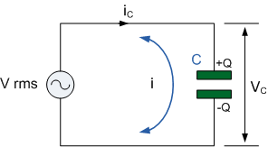
In the purely capacitive circuit above, the capacitor is connected directly
across the AC supply voltage. As the supply voltage increases and decreases,
the capacitor charges and discharges with respect to this change. We know
that the charging current is directly proportional to the rate of change of
the voltage across the plates with this rate of change at its greatest as
the supply voltage crosses over from its positive half cycle to its negative
half cycle or vice versa at points, 0o and 180o along the sine wave.
Consequently, the least voltage rate-of-change occurs when the AC sine wave
crosses over at its maximum positive peak ( +VMAX ) and its minimum negative
peak, ( -VMAX ). At these two positions within the cycle, the sinusoidal
voltage is constant, therefore its rate-of-change is zero, so dv/dt is zero,
resulting in zero current change within the capacitor. Thus when dv/dt = 0,
the capacitor acts as an open circuit, so i = 0 and this is shown below.
capacitance in ac circuits
In the purely capacitive circuit above, the capacitor is connected directly
across the AC supply voltage. As the supply voltage increases and decreases,
the capacitor charges and discharges with respect to this change. We know
that the charging current is directly proportional to the rate of change of
the voltage across the plates with this rate of change at its greatest as
the supply voltage crosses over from its positive half cycle to its negative
half cycle or vice versa at points, 0o and 180o along the sine wave.
Consequently, the least voltage rate-of-change occurs when the AC sine wave
crosses over at its maximum positive peak ( +VMAX ) and its minimum negative
peak, ( -VMAX ). At these two positions within the cycle, the sinusoidal
voltage is constant, therefore its rate-of-change is zero, so dv/dt is zero,
resulting in zero current change within the capacitor. Thus when dv/dt = 0,
the capacitor acts as an open circuit, so i = 0 and this is shown below.
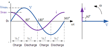 capacitance in ac circuits phasor diagram
At 0o the rate of change of the supply voltage is increasing in a positive
direction resulting in a maximum charging current at that instant in time.
As the applied voltage reaches its maximum peak value at 90o for a very
brief instant in time the supply voltage is neither increasing or decreasing
so there is no current flowing through the circuit.
As the applied voltage begins to decrease to zero at 180o, the slope of the
voltage is negative so the capacitor discharges in the negative direction.
At the 180o point along the line the rate of change of the voltage is at its
maximum again so maximum current flows at that instant and so on.
Then we can say that for capacitors in AC circuits the instantaneous current
is at its minimum or zero whenever the applied voltage is at its maximum and
likewise the instantaneous value of the current is at its maximum or peak
value when the applied voltage is at its minimum or zero.
From the waveform above, we can see that the current is leading the voltage
by 1/4 cycle or 90o as shown by the vector diagram. Then we can say that in
a purely capacitive circuit the alternating voltage lags the current by
90o.
We know that the current flowing through the capacitance in AC circuits is
in opposition to the rate of change of the applied voltage. But just like
resistors, capacitors also offer some form of resistance against the flow of
current. For capacitors in AC circuits opposition is known as Reactance, and
as we are dealing with capacitor circuits, it is therefore known as
Capacitive Reactance. Thus capacitance in AC circuits suffer from Capacitive
Reactance.
capacitance in ac circuits phasor diagram
At 0o the rate of change of the supply voltage is increasing in a positive
direction resulting in a maximum charging current at that instant in time.
As the applied voltage reaches its maximum peak value at 90o for a very
brief instant in time the supply voltage is neither increasing or decreasing
so there is no current flowing through the circuit.
As the applied voltage begins to decrease to zero at 180o, the slope of the
voltage is negative so the capacitor discharges in the negative direction.
At the 180o point along the line the rate of change of the voltage is at its
maximum again so maximum current flows at that instant and so on.
Then we can say that for capacitors in AC circuits the instantaneous current
is at its minimum or zero whenever the applied voltage is at its maximum and
likewise the instantaneous value of the current is at its maximum or peak
value when the applied voltage is at its minimum or zero.
From the waveform above, we can see that the current is leading the voltage
by 1/4 cycle or 90o as shown by the vector diagram. Then we can say that in
a purely capacitive circuit the alternating voltage lags the current by
90o.
We know that the current flowing through the capacitance in AC circuits is
in opposition to the rate of change of the applied voltage. But just like
resistors, capacitors also offer some form of resistance against the flow of
current. For capacitors in AC circuits opposition is known as Reactance, and
as we are dealing with capacitor circuits, it is therefore known as
Capacitive Reactance. Thus capacitance in AC circuits suffer from Capacitive
Reactance.
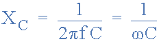 capacitance in ac circuits reactance
Where: F is in Hertz and C is in Farads. 2πƒ can also be expressed
collectively as the Greek letter Omega, ω to denote an angular frequency.
From the capacitive reactance formula above, it can be seen that if either
of the Frequency or Capacitance where to be increased the overall capacitive
reactance would decrease. As the frequency approaches infinity the
capacitors reactance would reduce to zero acting like a perfect conductor.
However, as the frequency approaches zero or DC, the capacitors reactance
would increase up to infinity, acting like a very large resistance. This
means then that capacitive reactance is “Inversely proportional” to
frequency for any given value of Capacitance and this shown below:
capacitance in ac circuits reactance
Where: F is in Hertz and C is in Farads. 2πƒ can also be expressed
collectively as the Greek letter Omega, ω to denote an angular frequency.
From the capacitive reactance formula above, it can be seen that if either
of the Frequency or Capacitance where to be increased the overall capacitive
reactance would decrease. As the frequency approaches infinity the
capacitors reactance would reduce to zero acting like a perfect conductor.
However, as the frequency approaches zero or DC, the capacitors reactance
would increase up to infinity, acting like a very large resistance. This
means then that capacitive reactance is “Inversely proportional” to
frequency for any given value of Capacitance and this shown below:
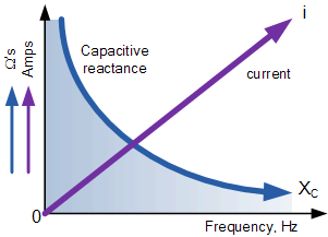 capacitive reactance against frequency
|
The capacitive reactance of the capacitor decreases as the frequency across
it increases therefore capacitive reactance is inversely proportional to
frequency.
The opposition to current flow, the electrostatic charge on the plates (its AC capacitance value) remains constant as it becomes easier for the capacitor to fully absorb the change in charge on its plates during each half cycle. |
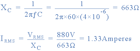 Answer Example No1
In AC circuits, the sinusoidal current through a capacitor, which leads the
voltage by 90o, varies with frequency as the capacitor is being constantly
charged and discharged by the applied voltage. The AC impedance of a
capacitor is known as Reactance and as we are dealing with capacitor
circuits, more commonly called Capacitive Reactance, XC
Answer Example No1
In AC circuits, the sinusoidal current through a capacitor, which leads the
voltage by 90o, varies with frequency as the capacitor is being constantly
charged and discharged by the applied voltage. The AC impedance of a
capacitor is known as Reactance and as we are dealing with capacitor
circuits, more commonly called Capacitive Reactance, XC
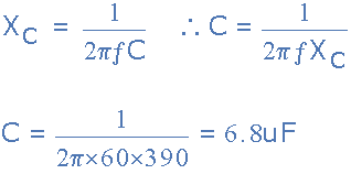 capacitance of a capacitor
This capacitive reactance is inversely proportional to frequency and
produces the opposition to current flow around a capacitive AC circuit as we
looked at in the AC Capacitance tutorial in the AC Theory section.
previousPrevious
Capacitors in Series
Next
Capacitive Voltage Divider
next
capacitance of a capacitor
This capacitive reactance is inversely proportional to frequency and
produces the opposition to current flow around a capacitive AC circuit as we
looked at in the AC Capacitance tutorial in the AC Theory section.
previousPrevious
Capacitors in Series
Next
Capacitive Voltage Divider
next