ESP32 WiFi Drv
#include <WiFi.h>
From: "https://docs.espressif.com/projects/esp-idf/en/latest/esp32/api-guides/wifi.html"
Wi-Fi Driver
ESP32 Wi-Fi Feature List
The following features are supported:
- 4 virtual Wi-Fi interfaces, which are STA, AP, Sniffer and reserved.
- Station-only mode, AP-only mode, station/AP-coexistence mode
- IEEE 802.11b, IEEE 802.11g, IEEE 802.11n, and APIs to configure the protocol mode
- WPA/WPA2/WPA3/WPA2-Enterprise/WPA3-Enterprise/WAPI/WPS and DPP
- AMSDU, AMPDU, HT40, QoS, and other key features
- Modem-sleep
- The Espressif-specific ESP-NOW protocol and Long Range mode, which supports
- up to 1 km of data traffic
- Up to 20 MBit/s TCP throughput and 30 MBit/s UDP throughput over the air
- Sniffer
- Both fast scan and all-channel scan
- Multiple antennas
- Channel state information
How To Write a Wi-Fi Application
Preparation
Generally, the most effective way to begin your own Wi-Fi application is to
select an example which is similar to your own application, and port the useful
part into your project. It is not a MUST, but it is strongly recommended that
you take some time to read this article first, especially if you want to program
a robust Wi-Fi application.
This article is supplementary to the Wi-Fi APIs/Examples. It describes the
principles of using the Wi-Fi APIs, the limitations of the current Wi-Fi API
implementation, and the most common pitfalls in using Wi-Fi. This article also
reveals some design details of the Wi-Fi driver. We recommend you to select an
example .
Setting Wi-Fi Compile-time Options
Refer to Wi-Fi Menuconfig.
Init Wi-Fi
Refer to ESP32 Wi-Fi station General Scenario and ESP32 Wi-Fi AP General
Scenario.
Start/Connect Wi-Fi
Refer to ESP32 Wi-Fi station General Scenario and ESP32 Wi-Fi AP General
Scenario.
Event-Handling
Generally, it is easy to write code in “sunny-day” scenarios, such as
WIFI_EVENT_STA_START and WIFI_EVENT_STA_CONNECTED. The hard part is to write
routines in “rainy-day” scenarios, such as WIFI_EVENT_STA_DISCONNECTED. Good
handling of “rainy-day” scenarios is fundamental to robust Wi-Fi applications.
Refer to ESP32 Wi-Fi Event Description, ESP32 Wi-Fi station General Scenario,
and ESP32 Wi-Fi AP General Scenario. See also an overview of event handling in
ESP-IDF.
Write Error-Recovery Routines Correctly at All Times
Just like the handling of “rainy-day” scenarios, a good error-recovery routine
is also fundamental to robust Wi-Fi applications. Refer to ESP32 Wi-Fi API
Error Code.
ESP32 Wi-Fi API Error Code
All of the ESP32 Wi-Fi APIs have well-defined return values, namely, the error
code. The error code can be categorized into:
- No errors, e.g., ESP_OK means that the API returns successfully.
- Recoverable errors, such as ESP_ERR_NO_MEM.
- Non-recoverable, non-critical errors.
- Non-recoverable, critical errors.
Whether the error is critical or not depends on the API and the application
scenario, and it is defined by the API user.
The primary principle to write a robust application with Wi-Fi
API is to always check the error code and write the error-handling code.
Generally, the error-handling code can be used:
For recoverable errors, in which case you can write a recoverable-error
code. For example, when esp_wifi_start() returns ESP_ERR_NO_MEM, the
recoverable-error code vTaskDelay can be called in order to get a microseconds’
delay for another try.
For non-recoverable, yet non-critical errors, in which case printing the
error code is a good method for error handling.
For non-recoverable and also critical errors, in which case “assert” may
be a good method for error handling. For example, if esp_wifi_set_mode() returns
ESP_ERR_WIFI_NOT_INIT, it means that the Wi-Fi driver is not initialized by
esp_wifi_init() successfully. You can detect this kind of error very quickly in
the application development phase.
In esp_err.h, ESP_ERROR_CHECK checks the return values. It is a rather
commonplace error-handling code and can be used as the default error-handling
code in the application development phase. However, it is strongly recommended
that API users write their own error-handling code.
ESP32 Wi-Fi API Parameter Initialization
When initializing struct parameters for the API, one of two approaches should be
followed:
Explicitly set all fields of the parameter.
Use get API to get current configuration first, then set application
specific fields.
Initializing or getting the entire structure is very important, because most of
the time the value 0 indicates that the default value is used. More fields may
be added to the struct in the future and initializing these to zero ensures the
application will still work correctly after ESP-IDF is updated to a new release.
ESP32 Wi-Fi Programming Model
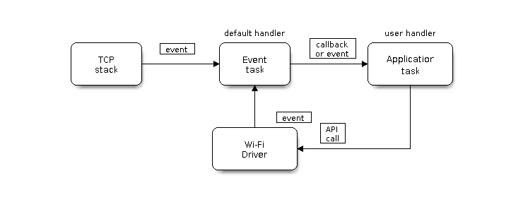 The ESP32 Wi-Fi programming model is depicted as follows:
Wi-Fi Programming Model
The Wi-Fi driver can be considered a black box that knows nothing about
high-layer code, such as the TCP/IP stack, application task, and event task.
The application task (code) generally calls Wi-Fi driver APIs to initialize
Wi-Fi and handles Wi-Fi events when necessary. Wi-Fi driver receives API calls,
handles them, and posts events to the application.
Wi-Fi event handling is based on the esp_event library. Events are sent by the
Wi-Fi driver to the default event loop. Application may handle these events in
callbacks registered using esp_event_handler_register(). Wi-Fi events are also
handled by esp_netif component to provide a set of default behaviors. For
example, when Wi-Fi station connects to an AP, esp_netif will automatically
start the DHCP client by default.
The ESP32 Wi-Fi programming model is depicted as follows:
Wi-Fi Programming Model
The Wi-Fi driver can be considered a black box that knows nothing about
high-layer code, such as the TCP/IP stack, application task, and event task.
The application task (code) generally calls Wi-Fi driver APIs to initialize
Wi-Fi and handles Wi-Fi events when necessary. Wi-Fi driver receives API calls,
handles them, and posts events to the application.
Wi-Fi event handling is based on the esp_event library. Events are sent by the
Wi-Fi driver to the default event loop. Application may handle these events in
callbacks registered using esp_event_handler_register(). Wi-Fi events are also
handled by esp_netif component to provide a set of default behaviors. For
example, when Wi-Fi station connects to an AP, esp_netif will automatically
start the DHCP client by default.
ESP32 Wi-Fi Event Description
WIFI_EVENT_WIFI_READY
The Wi-Fi driver will never generate this event, which, as a result, can be
ignored by the application event callback. This event may be removed in future
releases.
WIFI_EVENT_SCAN_DONE
The scan-done event is triggered by esp_wifi_scan_start() and will arise in the
following scenarios:
The scan is completed, e.g., the target AP is found successfully, or all
channels have been scanned.
The scan is stopped by esp_wifi_scan_stop().
The esp_wifi_scan_start() is called before the scan is completed. A new scan
will override the current scan and a scan-done event will be generated.
The scan-done event will not arise in the following scenarios:
It is a blocked scan.
The scan is caused by esp_wifi_connect().
Upon receiving this event, the event task does nothing. The application event
callback needs to call esp_wifi_scan_get_ap_num() and
esp_wifi_scan_get_ap_records() to fetch the scanned AP list and trigger the
Wi-Fi driver to free the internal memory which is allocated during the scan (do
not forget to do this!). Refer to ESP32 Wi-Fi Scan for a more detailed
description.
WIFI_EVENT_STA_START
If esp_wifi_start() returns ESP_OK and the current Wi-Fi mode is station or
station/AP, then this event will arise. Upon receiving this event, the event
task will initialize the LwIP network interface (netif). Generally, the
application event callback needs to call esp_wifi_connect() to connect to the
configured AP.
WIFI_EVENT_STA_STOP
If esp_wifi_stop() returns ESP_OK and the current Wi-Fi mode is station or
station/AP, then this event will arise. Upon receiving this event, the event
task will release the station’s IP address, stop the DHCP client, remove
TCP/UDP-related connections, and clear the LwIP station netif, etc. The
application event callback generally does not need to do anything.
WIFI_EVENT_STA_CONNECTED
If esp_wifi_connect() returns ESP_OK and the station successfully connects to
the target AP, the connection event will arise. Upon receiving this event, the
event task starts the DHCP client and begins the DHCP process of getting the IP
address. Then, the Wi-Fi driver is ready for sending and receiving data. This
moment is good for beginning the application work, provided that the application
does not depend on LwIP, namely the IP address. However, if the application is
LwIP-based, then you need to wait until the got ip event comes in.
WIFI_EVENT_STA_DISCONNECTED
This event can be generated in the following scenarios:
- When esp_wifi_disconnect() or esp_wifi_stop() is called and the station is
already connected to the AP.
- When esp_wifi_connect() is called, but the Wi-Fi driver fails to set up a
connection with the AP due to certain reasons, e.g., the scan fails to find
the target AP or the authentication times out. If there are more than one AP
with the same SSID, the disconnected event will be raised after the station
fails to connect all of the found APs.
- When the Wi-Fi connection is disrupted because of specific reasons, e.g.
, the station continuously loses N beacons, the AP kicks off the station, or
the AP’s authentication mode is changed.
Upon receiving this event, the default behaviors of the event task are:
- Shutting down the station’s LwIP netif.
- Notifying the LwIP task to clear the UDP/TCP connections which cause the
wrong status to all sockets. For socket-based applications, the application
callback can choose to close all sockets and re-create them, if necessary,
upon receiving this event.
The most common event handle code for this event in application is to call
esp_wifi_connect() to reconnect the Wi-Fi. However, if the event is raised
because esp_wifi_disconnect() is called, the application should not call
esp_wifi_connect() to reconnect. It is the application’s responsibility to
distinguish whether the event is caused by esp_wifi_disconnect() or other
reasons. Sometimes a better reconnection strategy is required. Refer to Wi-Fi
Reconnect and Scan When Wi-Fi Is Connecting.
Another thing that deserves attention is that the default behavior of LwIP is to
abort all TCP socket connections on receiving the disconnect. In mose cases, it
is not a problem. However, for some special applications, this may not be what
they want. Consider the following scenarios:
The application creates a TCP connection to maintain the application-level
keep-alive data that is sent out every 60 seconds.
Due to certain reasons, the Wi-Fi connection is cut off, and the
WIFI_EVENT_STA_DISCONNECTED is raised. According to the current
implementation, all TCP connections will be removed and the keep-alive
socket will be in a wrong status. However, since the application designer
believes that the network layer should ignore this error at the Wi-Fi layer,
the application does not close the socket.
Five seconds later, the Wi-Fi connection is restored because
esp_wifi_connect() is called in the application event callback function.
Moreover, the station connects to the same AP and gets the same IPV4 address
as before.
Sixty seconds later, when the application sends out data with the keep-alive
socket, the socket returns an error and the application closes the socket
and re-creates it when necessary.
In above scenarios, ideally, the application sockets and the network layer
should not be affected, since the Wi-Fi connection only fails temporarily and
recovers very quickly. The application can enable “Keep TCP connections when IP
changed” via LwIP menuconfig.
IP_EVENT_STA_GOT_IP
This event arises when the DHCP client successfully gets the IPV4 address from
the DHCP server, or when the IPV4 address is changed. The event means that
everything is ready and the application can begin its tasks (e.g., creating
sockets).
The IPV4 may be changed because of the following reasons:
The DHCP client fails to renew/rebind the IPV4 address, and the station’s
IPV4 is reset to 0.
The DHCP client rebinds to a different address.
The static-configured IPV4 address is changed.
Whether the IPV4 address is changed or not is indicated by the field ip_change
of ip_event_got_ip_t.
The socket is based on the IPV4 address, which means that, if the IPV4 changes,
all sockets relating to this IPV4 will become abnormal. Upon receiving this
event, the application needs to close all sockets and recreate the application
when the IPV4 changes to a valid one.
IP_EVENT_GOT_IP6
This event arises when the IPV6 SLAAC support auto-configures an address for the
ESP32, or when this address changes. The event means that everything is ready
and the application can begin its tasks, e.g., creating sockets.
IP_EVENT_STA_LOST_IP
This event arises when the IPV4 address becomes invalid.
IP_EVENT_STA_LOST_IP does not arise immediately after the Wi-Fi disconnects.
Instead, it starts an IPV4 address lost timer. If the IPV4 address is got before
ip lost timer expires, IP_EVENT_STA_LOST_IP does not happen. Otherwise, the
event arises when the IPV4 address lost timer expires.
Generally, the application can ignore this event, because it is just a debug
event to inform that the IPV4 address is lost.
WIFI_EVENT_AP_START
Similar to WIFI_EVENT_STA_START.
WIFI_EVENT_AP_STOP
Similar to WIFI_EVENT_STA_STOP.
WIFI_EVENT_AP_STACONNECTED
Every time a station is connected to ESP32 AP, the WIFI_EVENT_AP_STACONNECTED
will arise. Upon receiving this event, the event task will do nothing, and the
application callback can also ignore it. However, you may want to do something,
for example, to get the info of the connected STA.
WIFI_EVENT_AP_STADISCONNECTED
This event can happen in the following scenarios:
The application calls esp_wifi_disconnect(), or esp_wifi_deauth_sta(), to
manually disconnect the station.
The Wi-Fi driver kicks off the station, e.g., because the AP has not received
any packets in the past five minutes. The time can be modified by
esp_wifi_set_inactive_time().
The station kicks off the AP.
When this event happens, the event task will do nothing, but the application
event callback needs to do something, e.g., close the socket which is related to
this station.
WIFI_EVENT_AP_PROBEREQRECVED
This event is disabled by default. The application can enable it via API
esp_wifi_set_event_mask(). When this event is enabled, it will be raised each
time the AP receives a probe request.
WIFI_EVENT_STA_BEACON_TIMEOUT
If the station does not receive the beacon of the connected AP within the
inactive time, the beacon timeout happens, the WIFI_EVENT_STA_BEACON_TIMEOUT will arise.
The application can set inactive time via API esp_wifi_set_inactive_time().
WIFI_EVENT_CONNECTIONLESS_MODULE_WAKE_INTERVAL_START
The WIFI_EVENT_CONNECTIONLESS_MODULE_WAKE_INTERVAL_START will arise at the start
of connectionless module Interval. See connectionless module power save.
ESP32 Wi-Fi Station General Scenario
Below is a “big scenario” which describes some small scenarios in station mode:
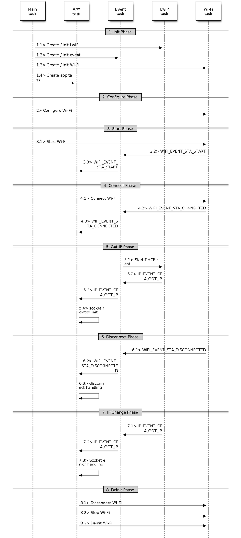 Sample Wi-Fi Event Scenarios in Station Mode
1. Wi-Fi/LwIP Init Phase
s1.1: The main task calls esp_netif_init() to create an LwIP core task and
initialize LwIP-related work.
s1.2: The main task calls esp_event_loop_create() to create a system Event
task and initialize an application event’s callback function. In the
scenario above, the application event’s callback function does nothing but
relaying the event to the application task.
s1.3: The main task calls esp_netif_create_default_wifi_ap() or
esp_netif_create_default_wifi_sta() to create default network interface
instance binding station or AP with TCP/IP stack.
s1.4: The main task calls esp_wifi_init() to create the Wi-Fi driver task
and initialize the Wi-Fi driver.
s1.5: The main task calls OS API to create the application task.
Step 1.1 ~ 1.5 is a recommended sequence that initializes a Wi-Fi-/LwIP-based
application. However, it is NOT a must-follow sequence, which means that you can
create the application task in step 1.1 and put all other initializations in the
application task. Moreover, you may not want to create the application task in
the initialization phase if the application task depends on the sockets. Rather,
you can defer the task creation until the IP is obtained.
2. Wi-Fi Configuration Phase
Once the Wi-Fi driver is initialized, you can start configuring the Wi-Fi driver.
In this scenario, the mode is station, so you may need to call
esp_wifi_set_mode() (WIFI_MODE_STA) to configure the Wi-Fi mode as station. You
can call other esp_wifi_set_xxx APIs to configure more settings, such as the
protocol mode, the country code, and the bandwidth. Refer to ESP32 Wi-Fi
Configuration.
Generally, the Wi-Fi driver should be configured before the Wi-Fi connection is
set up. But this is NOT mandatory, which means that you can configure the Wi-Fi
connection anytime, provided that the Wi-Fi driver is initialized successfully.
However, if the configuration does not need to change after the Wi-Fi connection
is set up, you should configure the Wi-Fi driver at this stage, because the
configuration APIs (such as esp_wifi_set_protocol()) will cause the Wi-Fi to
reconnect, which may not be desirable.
If the Wi-Fi NVS flash is enabled by menuconfig, all Wi-Fi configuration in this
phase, or later phases, will be stored into flash. When the board powers
on/reboots, you do not need to configure the Wi-Fi driver from scratch. You only
need to call esp_wifi_get_xxx APIs to fetch the configuration stored in flash
previously. You can also configure the Wi-Fi driver if the previous
configuration is not what you want.
3. Wi-Fi Start Phase
s3.1: Call esp_wifi_start() to start the Wi-Fi driver.
s3.2: The Wi-Fi driver posts WIFI_EVENT_STA_START to the event task; then,
the event task will do some common things and will call the application
event callback function.
s3.3: The application event callback function relays the
WIFI_EVENT_STA_START to the application task. We recommend that you call
esp_wifi_connect(). However, you can also call esp_wifi_connect() in other
phrases after the WIFI_EVENT_STA_START arises.
4. Wi-Fi Connect Phase
s4.1: Once esp_wifi_connect() is called, the Wi-Fi driver will start the
internal scan/connection process.
s4.2: If the internal scan/connection process is successful, the
WIFI_EVENT_STA_CONNECTED will be generated. In the event task, it starts the
DHCP client, which will finally trigger the DHCP process.
s4.3: In the above-mentioned scenario, the application event callback will
relay the event to the application task. Generally, the application needs
to do nothing, and you can do whatever you want, e.g., print a log.
In step 4.2, the Wi-Fi connection may fail because, for example, the password is
wrong, or the AP is not found. In a case like this, WIFI_EVENT_STA_DISCONNECTED
will arise and the reason for such a failure will be provided. For handling
events that disrupt Wi-Fi connection, please refer to phase 6.
5. Wi-Fi ‘Got IP’ Phase
s5.1: Once the DHCP client is initialized in step 4.2, the got IP phase will
begin.
s5.2: If the IP address is successfully received from the DHCP server, then
IP_EVENT_STA_GOT_IP will arise and the event task will perform common
handling.
s5.3: In the application event callback, IP_EVENT_STA_GOT_IP is relayed to
the application task. For LwIP-based applications, this event is very
special and means that everything is ready for the application to begin its
tasks, e.g., creating the TCP/UDP socket. A very common mistake is to
initialize the socket before IP_EVENT_STA_GOT_IP is received. DO NOT start
the socket-related work before the IP is received.
6. Wi-Fi Disconnect Phase
s6.1: When the Wi-Fi connection is disrupted, e.g., the AP is powered off or
the RSSI is poor, WIFI_EVENT_STA_DISCONNECTED will arise. This event may
also arise in phase 3. Here, the event task will notify the LwIP task to
clear/remove all UDP/TCP connections. Then, all application sockets will be
in a wrong status. In other words, no socket can work properly when this
event happens.
s6.2: In the scenario described above, the application event callback
function relays WIFI_EVENT_STA_DISCONNECTED to the application task. The
recommended actions are: 1) call esp_wifi_connect() to reconnect the Wi-Fi,
2) close all sockets, and 3) re-create them if necessary. For details,
please refer to WIFI_EVENT_STA_DISCONNECTED.
7 . Wi-Fi IP Change Phase
s7.1: If the IP address is changed, the IP_EVENT_STA_GOT_IP will arise with
“ip_change” set to true.
s7.2: This event is important to the application. When it occurs, the
timing is good for closing all created sockets and recreating them.
8. Wi-Fi Deinit Phase
s8.1: Call esp_wifi_disconnect() to disconnect the Wi-Fi connectivity.
s8.2: Call esp_wifi_stop() to stop the Wi-Fi driver.
s8.3: Call esp_wifi_deinit() to unload the Wi-Fi driver.
ESP32 Wi-Fi AP General Scenario
Below is a “big scenario” which describes some small scenarios in AP mode:
Sample Wi-Fi Event Scenarios in AP Mode
ESP32 Wi-Fi Scan
Currently, the esp_wifi_scan_start() API is supported only in station or
station/AP mode.
| Scan Type
|
|
|
| Mode
| Description
|
| Active Scan
| Scan by sending a probe request. The default scan is an active scan.
|
| Passive Scan
| No probe request is sent out. Just switch to the specific channel and wait
for a beacon. Application can enable it via the scan_type field of
wifi_scan_config_t.
|
| Foreground Scan
| This scan is applicable when there is no Wi-Fi connection in station mode.
Foreground or background scanning is controlled by the Wi-Fi driver and cannot
be configured by the application.
|
| Background Scan
| This scan is applicable when there is a Wi-Fi connection in station mode or
in station/AP mode. Whether it is a foreground scan or background scan depends
on the Wi-Fi driver and cannot be configured by the application.
|
| All-Channel Scan
| It scans all of the channels. If the channel field of wifi_scan_config_t
is set to 0, it is an all-channel scan.
|
| Specific Channel Scan
| It scans specific channels only. If the channel field of wifi_scan_config_t
set to 1-14, it is a specific-channel scan.
|
The scan modes in above table can be combined arbitrarily, so there are in total 8 different scans:
All-Channel Background Active Scan
All-Channel Background Passive Scan
All-Channel Foreground Active Scan
All-Channel Foreground Passive Scan
Specific-Channel Background Active Scan
Specific-Channel Background Passive Scan
Specific-Channel Foreground Active Scan
Specific-Channel Foreground Passive Scan
Scan Configuration
The scan type and other per-scan attributes are configured by
esp_wifi_scan_start().
The table below provides a detailed description of wifi_scan_config_t.
| Field
| Description
|
|
|
| ssid
| If the SSID is not NULL, it is only the AP with the same SSID that can be
scanned.
|
| bssid
| If the BSSID is not NULL, it is only the AP with the same BSSID that can be
scanned.
|
| channel
| If “channel” is 0, there will be an all-channel scan; otherwise, there will
be a specific-channel scan.
|
| show_hidden
| If “show_hidden” is 0, the scan ignores the AP with a hidden SSID; otherwise
, the scan considers the hidden AP a normal one.
|
| scan_type
| If “scan_type” is WIFI_SCAN_TYPE_ACTIVE, the scan is “active”; otherwise, it
is a “passive” one.
|
| scan_time
| This field is used to control how long the scan dwells on each channel.
For passive scans, scan_time.passive designates the dwell time for each channel.
For active scans, dwell times for each channel are listed in the table
below. Here, min is short for scan time.active.min and max is short for
scan_time.active.max.
- min=0, max=0: scan dwells on each channel for 120 ms.
- min>0, max=0: scan dwells on each channel for 120 ms.
- min=0, max>0: scan dwells on each channel for max ms.
- min>0, max>0: the minimum time the scan dwells on each channel is min
ms. If no AP is found during this time frame, the scan switches to the
next channel. Otherwise, the scan dwells on the channel for max ms.
If you want to improve the performance of the scan, you can try to modify
these two parameters.
|
There are also some global scan attributes which are configured by
API esp_wifi_set_config(), refer to Station Basic Configuration
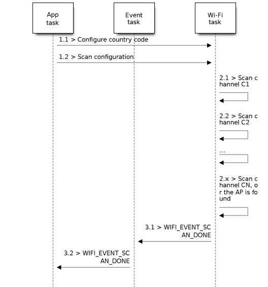
Scan All APs on All Channels (Foreground)
Scenario:
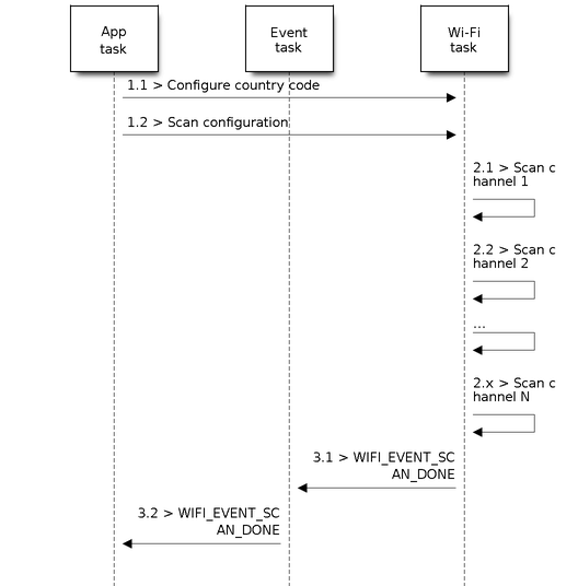 Foreground Scan of all Wi-Fi Channels
The scenario above describes an all-channel, foreground scan. The foreground scan can only occur in station mode where the station does not connect to any AP. Whether it is a foreground or background scan is totally determined by the Wi-Fi driver, and cannot be configured by the application.
Detailed scenario description:
Foreground Scan of all Wi-Fi Channels
The scenario above describes an all-channel, foreground scan. The foreground scan can only occur in station mode where the station does not connect to any AP. Whether it is a foreground or background scan is totally determined by the Wi-Fi driver, and cannot be configured by the application.
Detailed scenario description:
Scan Configuration Phase
- s1.1: Call esp_wifi_set_country() to set the country info if the default
country info is not what you want. Refer to Wi-Fi Country Code.
- s1.2: Call esp_wifi_scan_start() to configure the scan. To do so, you can
refer to Scan Configuration. Since this is an all-channel scan, just set
the SSID/BSSID/channel to 0.
Wi-Fi Driver’s Internal Scan Phase
- s2.1: The Wi-Fi driver switches to channel 1. In this case, the scan type is
WIFI_SCAN_TYPE_ACTIVE, and a probe request is broadcasted. Otherwise, the
Wi-Fi will wait for a beacon from the APs. The Wi-Fi driver will stay in
channel 1 for some time. The dwell time is configured in min/max time, with
the default value being 120 ms.
- s2.2: The Wi-Fi driver switches to channel 2 and performs the same operation
as in step 2.1.
- s2.3: The Wi-Fi driver scans the last channel N, where N is determined by
the country code which is configured in step 1.1.
Scan-Done Event Handling Phase
- s3.1: When all channels are scanned, WIFI_EVENT_SCAN_DONE will arise.
- s3.2: The application’s event callback function notifies the application
task that WIFI_EVENT_SCAN_DONE is received. esp_wifi_scan_get_ap_num() is
called to get the number of APs that have been found in this scan. Then, it
allocates enough entries and calls esp_wifi_scan_get_ap_records() to get the
AP records. Please note that the AP records in the Wi-Fi driver will be
freed once esp_wifi_scan_get_ap_records() is called. Do not call
esp_wifi_scan_get_ap_records() twice for a single scan-done event.
If esp_wifi_scan_get_ap_records() is not called when the scan-done event
occurs, the AP records allocated by the Wi-Fi driver will not be freed. So,
make sure you call esp_wifi_scan_get_ap_records(), yet only once.
Scan All APs on All Channels (Background)
Scenario:
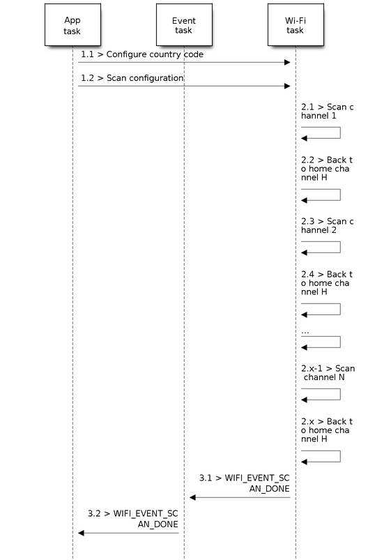 Background Scan of all Wi-Fi Channels
The scenario above is an all-channel background scan. Compared to Scan All APs
on All Channels (Foreground) , the difference in the all-channel background scan
is that the Wi-Fi driver will scan the back-to-home channel for 30 ms before it
switches to the next channel to give the Wi-Fi connection a chance to
transmit/receive data.
Background Scan of all Wi-Fi Channels
The scenario above is an all-channel background scan. Compared to Scan All APs
on All Channels (Foreground) , the difference in the all-channel background scan
is that the Wi-Fi driver will scan the back-to-home channel for 30 ms before it
switches to the next channel to give the Wi-Fi connection a chance to
transmit/receive data.
Scan for Specific AP on All Channels
Scenario:
 Scan of specific Wi-Fi Channels
This scan is similar to Scan All APs on All Channels (Foreground).
The differences are:
Scan of specific Wi-Fi Channels
This scan is similar to Scan All APs on All Channels (Foreground).
The differences are:
- s1.1: In step 1.2, the target AP will be configured to SSID/BSSID.
- s2.1 ~ s2.N: Each time the Wi-Fi driver scans an AP, it will check whether
it is a target AP or not. If the scan is WIFI_FAST_SCAN scan and the target
AP is found, then the scan-done event will arise and scanning will end;
otherwise, the scan will continue. Please note that the first scanned
channel may not be channel 1, because the Wi-Fi driver optimizes the
scanning sequence.
It is a possible situation that there are multiple APs that match the target AP
info, e.g., two APs with the SSID of “ap” are scanned. In this case, if the scan
is WIFI_FAST_SCAN, then only the first scanned “ap” will be found. If the scan
is WIFI_ALL_CHANNEL_SCAN, both “ap” will be found and the station will connect
the “ap” according to the configured strategy. Refer to Station Basic
Configuration.
You can scan a specific AP, or all of them, in any given channel. These two
scenarios are very similar.
Scan in Wi-Fi Connect
When esp_wifi_connect() is called, the Wi-Fi driver will try to scan the
configured AP first. The scan in “Wi-Fi Connect” is the same as Scan for
Specific AP On All Channels, except that no scan-done event will be generated
when the scan is completed. If the target AP is found, the Wi-Fi driver will
start the Wi-Fi connection; otherwise, WIFI_EVENT_STA_DISCONNECTED will be
generated. Refer to Scan for Specific AP On All Channels.
Scan in Blocked Mode
If the block parameter of esp_wifi_scan_start() is true, then the scan is a
blocked one, and the application task will be blocked until the scan is done.
The blocked scan is similar to an unblocked one, except that no scan-done event
will arise when the blocked scan is completed.
Parallel Scan
Two application tasks may call esp_wifi_scan_start()
at the same time, or the same application task calls esp_wifi_scan_start() before
it gets a scan-done event. Both scenarios can happen. However, the
Wi-Fi driver does not support multiple concurrent scans adequately.
As a result, concurrent scans should be avoided. Support for concurrent
scan will be enhanced in future releases, as the ESP32’s Wi-Fi functionality
improves continuously.
Scan When Wi-Fi Is Connecting
The esp_wifi_scan_start() fails immediately if the Wi-Fi is connecting, because
the connecting has higher priority than the scan. If scan fails because of
connecting, the recommended strategy is to delay for some time and retry scan
again. The scan will succeed once the connecting is completed.
However, the retry/delay strategy may not work all the time. Considering the
following scenarios:
The station is connecting a non-existing AP or it connects the existing AP
with a wrong password, it always raises the event
WIFI_EVENT_STA_DISCONNECTED.
The application calls esp_wifi_connect() to reconnect on receiving the
disconnect event.
Another application task, e.g., the console task, calls
esp_wifi_scan_start() to do scan, the scan always fails immediately because
the station keeps connecting.
When scan fails, the application simply delays for some time and retries the
scan.
In the above scenarios, the scan will never succeed because the connecting is in
process. So if the application supports similar scenario, it needs to implement
a better reconnection strategy. For example:
- The application can choose to define a maximum continuous reconnection counter and stop reconnecting once the counter reaches the maximum.
- The application can choose to reconnect immediately in the first N continuous reconnection, then give a delay sometime and reconnect again.
The application can define its own reconnection strategy to avoid the scan
starve to death. Refer to .
ESP32 Wi-Fi Station Connecting Scenario
This scenario depicts the case if only one target AP is found in the scan phase.
For scenarios where more than one AP with the same SSID is found, refer to
ESP32 Wi-Fi Station Connecting When Multiple APs Are Found.
Generally, the application can ignore the connecting process. Below is a brief
introduction to the process for those who are really interested.
Scenario:
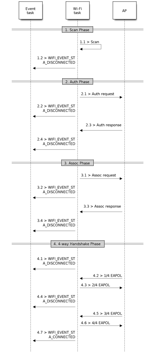 Wi-Fi Station Connecting Process
Scan Phase
- s1.1: The Wi-Fi driver begins scanning in “Wi-Fi Connect”. Refer to Scan in Wi-Fi Connect for more details.
- s1.2: If the scan fails to find the target AP, WIFI_EVENT_STA_DISCONNECTED will arise and the reason code will be WIFI_REASON_NO_AP_FOUND. Refer to Wi-Fi Reason Code.
Auth Phase
- s2.1: The authentication request packet is sent and the auth timer is enabled.
- s2.2: If the authentication response packet is not received before the
authentication timer times out, WIFI_EVENT_STA_DISCONNECTED
will arise and the reason code will be WIFI_REASON_AUTH_EXPIRE. Refer to Wi-Fi Reason Code.
- s2.3: The auth-response packet is received and the auth-timer is stopped.
- s2.4: The AP rejects authentication in the response and
WIFI_EVENT_STA_DISCONNECTED arises, while the reason code is
WIFI_REASON_AUTH_FAIL or the reasons specified by the AP. Refer to
Wi-Fi Reason Code.
Association Phase
- s3.1: The association request is sent and the association timer is enabled.
- s3.2: If the association response is not received before the association timer times out, WIFI_EVENT_STA_DISCONNECTED will arise and the reason code will be WIFI_REASON_ASSOC_EXPIRE. Refer to Wi-Fi Reason Code.
- s3.3: The association response is received and the association timer is stopped.
- s3.4: The AP rejects the association in the response and WIFI_EVENT_STA_DISCONNECTED arises, while the reason code is the one specified in the association response. Refer to Wi-Fi Reason Code.
Four-way Handshake Phase
- s4.1: The handshake timer is enabled, and the 1/4 EAPOL is not received before the handshake timer expires. WIFI_EVENT_STA_DISCONNECTED will arise and the reason code will be WIFI_REASON_HANDSHAKE_TIMEOUT. Refer to Wi-Fi Reason Code.
- s4.2: The 1/4 EAPOL is received.
- s4.3: The station replies 2/4 EAPOL.
- s4.4: If the 3/4 EAPOL is not received before the handshake timer expires, WIFI_EVENT_STA_DISCONNECTED will arise and the reason code will be WIFI_REASON_HANDSHAKE_TIMEOUT. Refer to Wi-Fi Reason Code.
- s4.5: The 3/4 EAPOL is received.
- s4.6: The station replies 4/4 EAPOL.
- s4.7: The station raises WIFI_EVENT_STA_CONNECTED.
Wi-Fi Reason Code
The table below shows the reason-code defined in ESP32. The first column is the
macro name defined in esp_wifi_types.h. The common prefix WIFI_REASON is removed
, which means that UNSPECIFIED actually stands for WIFI_REASON_UNSPECIFIED and
so on. The second column is the value of the reason. The third column is the
standard value to which this reason is mapped in section 9.4.1.7 of
IEEE 802.11-2020. (For more information, refer to the standard mentioned above.)
The last column describes the reason.
| Reason code | Value | Mapped To
| Description
|
| UNSPECIFIED
| 1
| 1
| Generally, it means an internal failure, e.g., the memory runs out, the
internal TX fails, or the reason is received from the remote side.
|
| AUTH_EXPIRE
| 2
| 2
| The previous authentication is no longer valid.
For the ESP station, this reason is reported when:
- auth is timed out.
- the reason is received from the AP.
For the ESP AP, this reason is reported when:
- the AP has not received any packets from the station in the past five minutes.
- the AP is stopped by calling esp_wifi_stop().
- the station is de-authed by calling esp_wifi_deauth_sta().
|
| AUTH_LEAVE
| 3
| 3
|
De-authenticated, because the sending station is leaving (or has left).
For the ESP station, this reason is reported when:
- it is received from the AP.
|
| ASSOC_EXPIRE
| 4
| 4
| Disassociated due to inactivity.
For the ESP station, this reason is reported when:
- it is received from the AP.
For the ESP AP, this reason is reported when:
- the AP has not received any packets from the station in the past five minutes.
- the AP is stopped by calling esp_wifi_stop().
- the station is de-authed by calling esp_wifi_deauth_sta().
|
| ASSOC_TOOMANY
| 5
| 5
| Disassociated, because the AP is unable to handle all currently associated STAs
at the same time.
For the ESP station, this reason is reported when:
- it is received from the AP.
For the ESP AP, this reason is reported when:
- the stations associated with the AP reach the maximum number that the AP can
support.
|
| NOT_AUTHED
| 6
| 6
| Class-2 frame received from a non-authenticated STA.
For the ESP station, this reason is reported when:
- it is received from the AP.
For the ESP AP, this reason is reported when:
- the AP receives a packet with data from a non-authenticated station.
|
| NOT_ASSOCED
| 7
| 7
| Class-3 frame received from a non-associated STA.
For the ESP station, this reason is reported when:
- it is received from the AP.
For the ESP AP, this reason is reported when:
- the AP receives a packet with data from a non-associated station.
|
| ASSOC_LEAVE
| 8
| 8
| Disassociated, because the sending station is leaving (or has left) BSS.
For the ESP station, this reason is reported when:
- it is received from the AP.
- the station is disconnected by esp_wifi_disconnect() and other APIs.
|
| ASSOC_NOT_AUTHED
| 9
| 9
| station requesting (re)association is not authenticated by the responding STA.
For the ESP station, this reason is reported when:
- it is received from the AP.
For the ESP AP, this reason is reported when:
- the AP receives packets with data from an associated, yet not authenticated, station.
|
| DISASSOC_PWRCAP_BAD
| 10
| 10
| Disassociated, because the information in the
Power Capability element is unacceptable.
For the ESP station, this reason is reported when:
- it is received from the AP.
|
| DISASSOC_SUPCHAN_BAD
| 11
| 11
| Disassociated, because the information in
the Supported Channels element is unacceptable.
For the ESP station, this reason is reported when:
- it is received from the AP.
|
| IE_INVALID
| 13
| 13
| Invalid element, i.e., an element whose
content does not meet the specifications of
the Standard in frame formats clause.
For the ESP station, this reason is reported when:
- it is received from the AP.
For the ESP AP, this reason is reported when:
- the AP parses a wrong WPA or RSN IE.
|
| MIC_FAILURE
| 14
| 14
| Message integrity code (MIC) failure.
For the ESP station, this reason is reported when:
- it is received from the AP.
|
| 4WAY_HANDSHAKE_TIMEOUT
| 15
| 15
| Four-way handshake times out. For legacy
reasons, in ESP this reason code is replaced
with WIFI_REASON_HANDSHAKE_TIMEOUT.
For the ESP station, this reason is reported when:
- the handshake times out.
- it is received from the AP.
|
| GROUP_KEY_UPDATE_TIMEOUT
| 16
| 16
| Group-Key Handshake times out.
For the ESP station, this reason is reported when:
- it is received from the AP.
|
| IE_IN_4WAY_DIFFERS
| 17
| 17
| The element in the four-way handshake is
different from the (Re-)Association
Request/Probe and Response/Beacon frame.
For the ESP station, this reason is reported when:
- it is received from the AP.
- the station finds that the four-way
handshake IE differs from the IE in the (Re-)Association
Request/Probe and Response/Beacon frame.
|
| GROUP_CIPHER_INVALID
| 18
| 18
| Invalid group cipher.
For the ESP station, this reason is reported when:
- it is received from the AP.
|
| PAIRWISE_CIPHER_INVALID
| 19
| 19
| Invalid pairwise cipher.
For the ESP station, this reason is reported when:
- it is received from the AP.
|
| AKMP_INVALID
| 20
| 20
| Invalid AKMP.
For the ESP station, this reason is reported
when: - it is received from the AP.
|
| UNSUPP_RSN_IE_VERSION
| 21
| 21
| Unsupported RSNE version.
For the ESP station, this reason is reported
when:
- it is received from the AP.
|
| INVALID_RSN_IE_CAP
| 22
| 22
| Invalid RSNE capabilities.
For the ESP station, this reason is reported
when:
- it is received from the AP.
|
| 802_1X_AUTH_FAILED
| 23
| 23
| IEEE 802.1X. authentication failed.
For the ESP station, this reason is reported
when:
- it is received from the AP.
For the ESP AP, this reason is reported when:
- IEEE 802.1X. authentication fails.
|
| CIPHER_SUITE_REJECTED
| 24
| 24
| Cipher suite rejected due to security policies.
For the ESP station, this reason is reported
when:
- it is received from the AP.
|
| TDLS_PEER_UNREACHABLE
| 25
| 25
| TDLS direct-link teardown due to TDLS peer
STA unreachable via the TDLS direct link.
|
| TDLS_UNSPECIFIED
| 26
| 26
| TDLS direct-link teardown for unspecified
reason.
|
| SSP_REQUESTED_DISASSOC
| 27
| 27
| Disassociated because session terminated
by SSP request.
|
| NO_SSP_ROAMING_AGREEMENT
| 28
| 28
| Disassociated because of lack of SSP
roaming agreement.
|
| BAD_CIPHER_OR_AKM
| 29
| 29
| Requested service rejected because of SSP
cipher suite or AKM requirement.
|
| NOT_AUTHORIZED_THIS_LOCATION
| 30
| 30
| Requested service not authorized in this
location.
|
| SERVICE_CHANGE_PRECLUDES_TS
| 31
| 31
| TS deleted because QoS AP lacks sufficient
bandwidth for this QoS STA due to a change
in BSS service characteristics or operational
mode (e.g., an HT BSS change from 40 MHz channel to 20 MHz channel).
|
| UNSPECIFIED_QOS
| 32
| 32
| Disassociated for unspecified, QoS-related
reason.
|
| NOT_ENOUGH_BANDWIDTH
| 33
| 33
| Disassociated because QoS AP lacks
sufficient bandwidth for this QoS STA.
|
| MISSING_ACKS
| 34
| 34
| Disassociated because excessive number of
frames need to be acknowledged, but are
not acknowledged due to AP transmissions
and/or poor channel conditions.
|
| EXCEEDED_TXOP
| 35
| 35
| Disassociated because STA is transmitting
outside the limits of its TXOPs.
|
| STA_LEAVING
| 36
| 36
| Requesting STA is leaving the BSS (or
resetting).
|
| END_BA
| 37
| 37
| Requesting STA is no longer using the
stream or session.
|
| UNKNOWN_BA
| 38
| 38
| Requesting STA received frames using a
mechanism for which a setup has not been
completed.
|
| TIMEOUT
| 39
| 39
| Requested from peer STA due to timeout
|
| Reserved
| 40 ~ 45
| 40 ~ 45
|
| PEER_INITIATED
| 46
| 46
| In a Disassociation frame: Disassociated
because authorized access limit reached.
|
| AP_INITIATED
| 47
| 47
| In a Disassociation frame: Disassociated
due to external service requirements.
|
| INVALID_FT_ACTION_FRAME_COUNT
| 48
| 48
| Invalid FT Action frame count.
|
| INVALID_PMKID
| 49
| 49
| Invalid pairwise master key identifier
(PMKID).
|
| INVALID_MDE
| 50
| 50
| Invalid MDE.
|
| INVALID_FTE
| 51
| 51
| Invalid FTE
|
| TRANSMISSION_LINK_ESTABLISHMENT_FAILED
| 67
| 67
| Transmission link establishment in
alternative channel failed.
|
| ALTERATIVE_CHANNEL_OCCUPIED
| 68
| 68
| The alternative channel is occupied.
|
| BEACON_TIMEOUT
| 200
| reserved
| Espressif-specific Wi-Fi reason code: when
the station loses N beacons continuously, it
will disrupt the connection and report this
reason.
|
| NO_AP_FOUND
| 201
| reserved
| Espressif-specific Wi-Fi reason code: when
the station fails to scan the target AP, this
reason code will be reported.
|
| AUTH_FAIL
| 202
| reserved
| Espressif-specific Wi-Fi reason code: the
authentication fails, but not because of a
timeout.
|
| ASSOC_FAIL
| 203
| reserved
| Espressif-specific Wi-Fi reason code: the
association fails, but not because of
ASSOC_EXPIRE or ASSOC_TOOMANY.
|
| HANDSHAKE_TIMEOUT
| 204
| reserved
| Espressif-specific Wi-Fi reason code: the
handshake fails for the same reason as that
in WIFI_REASON_4WAY_HANDSHAKE_TIMEOUT.
|
| CONNECTION_FAIL
| 205
| reserved
| Espressif-specific Wi-Fi reason code: the
connection to the AP has failed.
|
Wi-Fi Reason code related to wrong password
The table below shows the Wi-Fi reason-code may related to wrong password.
| Reason code | Value | Description
|
| 4WAY_HANDSHAKE_TIMEOUT
| 15
| Four-way handshake times out. Setting
wrong password when STA connecting to
an encrpyted AP.
|
| NO_AP_FOUND
| 201
| This may related to wrong password in the
two scenarios:
- Setting password when STA connecting to an unencrypted AP.
- Doesn’t setting password when STA connecting to an encrypted AP.
|
| HANDSHAKE_TIMEOUT
| 204
| Four-way handshake fails.
|
Wi-Fi Reason code related to low RSSI
The table below shows the Wi-Fi reason-code may related to low RSSI.
| Reason code | Value | Description
|
| NO_AP_FOUND
| 201
| The station fails to scan the target AP due to low
RSSI
|
| HANDSHAKE_TIMEOUT
| 204
| Four-way handshake fails.
|
ESP32 Wi-Fi Station Connecting When Multiple APs Are Found
This scenario is similar as ESP32 Wi-Fi Station Connecting Scenario. The
difference is that the station will not raise the event
WIFI_EVENT_STA_DISCONNECTED unless it fails to connect all of the found APs.
Wi-Fi Reconnect
The station may disconnect due to many reasons, e.g., the connected AP is
restarted. It is the application’s responsibility to reconnect. The recommended
reconnection strategy is to call esp_wifi_connect() on receiving event
WIFI_EVENT_STA_DISCONNECTED.
Sometimes the application needs more complex reconnection strategy:
If the disconnect event is raised because the esp_wifi_disconnect() is
called, the application may not want to do the reconnection.
If the esp_wifi_scan_start() may be called at anytime, a better reconnection
strategy is necessary. Refer to Scan When Wi-Fi Is Connecting.
Another thing that need to be considered is that the reconnection may not
connect the same AP if there are more than one APs with the same SSID. The
reconnection always select current best APs to connect.
Wi-Fi Beacon Timeout
The beacon timeout mechanism is used by ESP32 station to detect whether the AP
is alive or not. If the station does not receive the beacon of the connected AP
within the inactive time, the beacon timeout happens. The application can set
inactive time via API esp_wifi_set_inactive_time().
After the beacon times out, the station sends 5 probe requests to the AP. If
still no probe response or beacon is received from AP, the station disconnects
from the AP and raises the event WIFI_EVENT_STA_DISCONNECTED.
It should be considered that the timer used for beacon timeout will be reset
during the scanning process. It means that the scan process will affect the
triggering of the event WIFI_EVENT_STA_BEACON_TIMEOUT.
ESP32 Wi-Fi Configuration
All configurations will be stored into flash when the Wi-Fi NVS is enabled;
otherwise, refer to Wi-Fi NVS Flash.
Wi-Fi Mode
Call esp_wifi_set_mode() to set the Wi-Fi mode.
| Mode | Description
|
| WIFI_MODE_NULL
| NULL mode: in this mode, the internal data struct is not allocated to the
station and the AP, while both the station and AP interfaces are not initialized
for RX/TX Wi-Fi data. Generally, this mode is used for Sniffer, or when you only
want to stop both the station and the AP without calling esp_wifi_deinit() to
unload the whole Wi-Fi driver.
|
| WIFI_MODE_STA
| Station mode: in this mode, esp_wifi_start() will init the internal station
data, while the station’s interface is ready for the RX and TX Wi-Fi data. After
esp_wifi_connect(), the station will connect to the target AP.
|
| WIFI_MODE_AP
| AP mode: in this mode, esp_wifi_start() will init the internal AP data,
while the AP’s interface is ready for RX/TX Wi-Fi data. Then, the Wi-Fi driver
starts broad-casting beacons, and the AP is ready to get connected to other
stations.
|
| WIFI_MODE_APSTA
| Station/AP coexistence mode: in this mode, esp_wifi_start() will
simultaneously init both the station and the AP. This is done in station mode
and AP mode. Please note that the channel of the external AP, which the ESP
station is connected to, has higher priority over the ESP AP channel.
|
Station Basic Configuration
API esp_wifi_set_config() can be used to configure the station. And the
configuration will be stored in NVS. The table below describes the fields in
detail.
| Field | Description
|
td>ssid
td>This is the SSID of the target AP, to which the station wants to connect.
td>password
td>Password of the target AP.
| scan_method
| For WIFI_FAST_SCAN scan, the scan ends when the first matched AP is found.
For WIFI_ALL_CHANNEL_SCAN, the scan finds all matched APs on all channels. The
default scan is WIFI_FAST_SCAN.
|
| bssid_set
| If bssid_set is 0, the station connects to the AP whose SSID is the same as
the field “ssid”, while the field “bssid” is ignored. In all other cases, the
station connects to the AP whose SSID is the same as the “ssid” field, while its
BSSID is the same the “bssid” field .
|
| bssid
| This is valid only when bssid_set is 1; see field “bssid_set”.
|
| channel
| If the channel is 0, the station scans the channel 1 ~ N to search for the
target AP; otherwise, the station starts by scanning the channel whose value is
the same as that of the “channel” field, and then scans others to find the
target AP. If you do not know which channel the target AP is running on, set it
to 0.
|
| sort_method
| This field is only for WIFI_ALL_CHANNEL_SCAN.
If the sort_method is WIFI_CONNECT_AP_BY_SIGNAL, all matched APs are sorted by
signal, and the AP with the best signal will be connected firstly. For example,
the station wants to connect an AP whose SSID is “apxx”. If the scan finds two
APs whose SSID equals to “apxx”, and the first AP’s signal is -90 dBm while the
second AP’s signal is -30 dBm, the station connects the second AP firstly, and
it would not connect the first one unless it fails to connect the second one.
If the sort_method is WIFI_CONNECT_AP_BY_SECURITY, all matched APs are sorted by
security. For example, the station wants to connect an AP whose SSID is “apxx”.
If the scan finds two APs whose SSID is “apxx”, and the security of the first
found AP is open while the second one is WPA2, the station connects to the
second AP firstly, and it would not connect the first one unless it fails to
connect the second one.
|
| threshold
| The threshold is used to filter the found AP. If the RSSI or security mode
is less than the configured threshold, the AP will be discarded.
If the RSSI is set to 0, it means the default threshold and the default RSSI
threshold are -127 dBm. If the authmode threshold is set to 0, it means the
default threshold and the default authmode threshold are open.
|
Attention
WEP/WPA security modes are deprecated in IEEE 802.11-2016 specifications and are recommended not to be used. These modes can be rejected using authmode threshold by setting threshold as WPA2 by threshold.authmode as WIFI_AUTH_WPA2_PSK.
AP Basic Configuration
API esp_wifi_set_config() can be used to configure the AP. And the configuration
will be stored in NVS. The table below describes the fields in detail.
| Field | Description
|
| ssid
| SSID of AP; if the ssid[0] is 0xFF and ssid[1] is 0xFF, the AP defaults the
SSID to ESP_aabbcc, where “aabbcc” is the last three bytes of the AP MAC.
|
| password
| Password of AP; if the auth mode is WIFI_AUTH_OPEN, this field will be
ignored.
|
| ssid_len
| Length of SSID; if ssid_len is 0, check the SSID until there is a
termination character. If ssid_len > 32, change it to 32; otherwise, set the
SSID length according to ssid_len.
|
| channel
| Channel of AP; if the channel is out of range, the Wi-Fi driver defaults the
channel to channel 1. So, please make sure the channel is within the required
range. For more details, refer to Wi-Fi Country Code.
|
| authmode
| Auth mode of ESP AP; currently, ESP Wi-Fi does not support AUTH_WEP. If the
authmode is an invalid value, AP defaults the value to WIFI_AUTH_OPEN.
|
| ssid_hidden
| If ssid_hidden is 1, AP does not broadcast the SSID; otherwise, it does
broadcast the SSID.
|
| max_connection
| Currently, ESP Wi-Fi supports up to 10 Wi-Fi connections. If max_connection
> 10, AP defaults the value to 10.
|
| beacon_interval
| Beacon interval; the value is 100 ~ 60000 ms, with default value being 100
ms. If the value is out of range, AP defaults it to 100 ms.
|
Wi-Fi Protocol Mode
Currently, the ESP-IDF supports the following protocol modes:
| Protocol Mode | Description
|
| 802.11b
| Call esp_wifi_set_protocol(ifx, WIFI_PROTOCOL_11B) to set the station/AP to
802.11b-only mode.
|
| 802.11bg
| Call esp_wifi_set_protocol(ifx, WIFI_PROTOCOL_11B|WIFI_PROTOCOL_11G) to set
the station/AP to 802.11bg mode.
|
| 802.11g
| Call esp_wifi_set_protocol(ifx, WIFI_PROTOCOL_11B|WIFI_PROTOCOL_11G) and
esp_wifi_config_11b_rate(ifx, true) to set the station/AP to 802.11g mode.
|
| 802.11bgn
| Call esp_wifi_set_protocol( ifx, WIFI_PROTOCOL_11B | WIFI_PROTOCOL_11G
| WIFI_PROTOCOL_11N) to set the station/ AP to BGN mode.
|
| 802.11gn
| Call esp_wifi_set_protocol(ifx, WIFI_PROTOCOL_11B|WIFI_PROTOCOL_11G |
WIFI_PROTOCOL_11N) and esp_wifi_config_11b_rate(ifx, true) to set the
station/AP to 802.11gn mode.
|
| 802.11 BGNLR
| Call esp_wifi_set_protocol(ifx, WIFI_PROTOCOL_11B| WIFI_PROTOCOL_11G.|
WIFI_PROTOCOL_11N|WIFI_PROTOCOL_LR) to set the station/AP to BGN and the LR
mode.
|
| 802.11 LR
| Call esp_wifi_set_protocol(ifx, WIFI_PROTOCOL_LR) to set the station/AP
only to the LR mode.
This mode is an Espressif-patented mode which can achieve a one-kilometer line
of sight range. Please make sure both the station and the AP are connected to an
ESP device.
|
Long Range (LR)
Long Range (LR) mode is an Espressif-patented Wi-Fi mode which can achieve a
one-kilometer line of sight range. Compared to the traditional 802.11b mode, it
has better reception sensitivity, stronger anti-interference ability, and longer
transmission distance.
LR Compatibility
Since LR is Espressif-unique Wi-Fi mode, only ESP32 devices can transmit and
receive the LR data. In other words, the ESP32 device should NOT transmit the
data in LR data rate if the connected device does not support LR. The application
can achieve this by configuring suitable Wi-Fi mode. If the negotiated mode
supports LR, the ESP32 may transmit data in LR rate. Otherwise, ESP32 will
transmit all data in traditional Wi-Fi data rate.
The following table depicts the Wi-Fi mode negotiation:
| APSTA | BGN | BG | B |
BGNLR | BGLR | BLR | LR
|
| BGN
| BGN
| BG
| B
| BGN
| BG
| B
|
|
| BG
| BG
| BG
| B
| BG
| BG
| B
|
|
| B
| B
| B
| B
| B
| B
| B
|
|
| BGNLR
|
|
|
| BGNLR
| BGLR
| BLR
| LR
|
| BGLR
|
|
|
| BGLR
| BGLR
| BLR
| LR
|
| BLR
|
|
|
| BLR
| BLR
| BLR
| LR
|
| LR
|
|
|
| LR
| LR
| LR
| LR
|
In the above table, the row is the Wi-Fi mode of AP and the column is the Wi-Fi
mode of station. The “-” indicates Wi-Fi mode of the AP and station are not
compatible.
According to the table, the following conclusions can be drawn:
- For LR-enabled AP of ESP32, it is incompatible with traditional 802.11 mode,
because the beacon is sent in LR mode.
- For LR-enabled station of ESP32 whose mode is NOT LR-only mode, it is
compatible with traditional 802.11 mode.
- If both station and AP are ESP32 devices and both of them have enabled LR
mode, the negotiated mode supports LR.
If the negotiated Wi-Fi mode supports both traditional 802.11 mode and LR mode,
it is the Wi-Fi driver’s responsibility to automatically select the best data
rate in different Wi-Fi modes and the application can ignore it.
LR Impacts to Traditional Wi-Fi Device
The data transmission in LR rate has no impacts on the traditional Wi-Fi device
because:
- The CCA and backoff process in LR mode are consistent with 802.11 specification.
- The traditional Wi-Fi device can detect the LR signal via CCA and do backoff.
In other words, the transmission impact in LR mode is similar to that in 802.11b
mode.
LR Transmission Distance
The reception sensitivity gain of LR is about 4 dB larger than that of the
traditional 802.11b mode. Theoretically, the transmission distance is about 2 to
2.5 times the distance of 11B.
LR Throughput
The LR rate has very limited throughput, because the raw PHY data rate LR is
1/2 Mbps and 1/4 Mbps.
When to Use LR
The general conditions for using LR are:
- Both the AP and station are Espressif devices.
- Long distance Wi-Fi connection and data transmission is required.
- Data throughput requirements are very small, such as remote device control.
Wi-Fi Country Code
Call esp_wifi_set_country() to set the country info. The table below describes
the fields in detail. Please consult local 2.4 GHz RF operating regulations
before configuring these fields.
| Field | Description
|
| cc[3]
| Country code string. This attribute identifies the country or noncountry
entity in which the station/AP is operating. If it is a country, the first two
octets of this string is the two-character country info as described in the
document ISO/IEC3166-1. The third octect is one of the following:
- an ASCII space character, which means the regulations under which the station/AP is operating encompass all environments for the current frequency band in the country.
- an ASCII ‘O’ character, which means the regulations under which the station/AP is operating are for an outdoor environment only.
- an ASCII ‘I’ character, which means the regulations under which the station/AP is operating are for an indoor environment only.
- an ASCII ‘X’ character, which means the station/AP is operating under a noncountry entity. The first two octets of the noncountry entity is two ASCII ‘XX’ characters.
- the binary representation of the Operating Class table number currently in use. Refer to Annex E of IEEE Std 802.11-2020.
|
| schan
| Start channel. It is the minimum channel number of the regulations under
which the station/AP can operate.
|
| nchan
| Total number of channels as per the regulations. For example, if the
schan=1, nchan=13, then the station/AP can send data from channel 1 to 13.
|
| policy
| Country policy. This field controls which country info will be used if the
configured country info is in conflict with the connected AP’s. For more details
on related policies, see the following section.
|
The default country info is:
wifi_country_t config = {
.cc = "01",
.schan = 1,
.nchan = 11,
.policy = WIFI_COUNTRY_POLICY_AUTO,
};
If the Wi-Fi Mode is station/AP coexist mode, they share the same configured
country info. Sometimes, the country info of AP, to which the station is
connected, is different from the country info of configured. For example, the
configured station has country info:
wifi_country_t config = {
.cc = "JP",
.schan = 1,
.nchan = 14,
.policy = WIFI_COUNTRY_POLICY_AUTO,
};
but the connected AP has country info:
wifi_country_t config = {
.cc = "CN",
.schan = 1,
.nchan = 13,
};
then country info of connected AP’s is used.
The following table depicts which country info is used in different Wi-Fi modes
and different country policies, and it also describes the impact on active scan.
| Wi-Fi Mode | Policy | Description
|
| Station
| WIFI_COUNTRY_POLICY_AUTO
| If the connected AP has country IE
in its beacon, the country info
equals to the country info in
beacon. Otherwise, use the default country info.
For scan:
- Use active scan from 1 to 11 and use passive scan from 12 to 14.
Always keep in mind that if an AP
with hidden SSID and station is set
to a passive scan channel, the
passive scan will not find it. In other
words, if the application hopes to
find the AP with hidden SSID in
every channel, the policy of country info should be configured to
WIFI_COUNTRY_POLICY_MANUAL.
|
| Station
| WIFI_COUNTRY_POLICY_MANUAL
| Always use the configured country info.
For scan:
- Use active scan from schan to schan+nchan-1.
|
| AP
| WIFI_COUNTRY_POLICY_AUTO
| Always use the configured country info.
|
| AP
| WIFI_COUNTRY_POLICY_MANUAL
| Always use the configured country info.
|
| Station/AP-coexistence
| WIFI_COUNTRY_POLICY_AUTO
| Station: Same as station mode with policy WIFI_COUNTRY_POLICY_AUTO. AP: If
the station does not connect to any external AP, the AP uses the configured
country info. If the station connects to an external AP, the AP has the
same country info as the station.
|
| Station/AP-coexistence
| WIFI_COUNTRY_POLICY_MANUAL
| Station: Same as station mode with policy
WIFI_COUNTRY_POLICY_MANUAL.
AP: Same as AP mode with policy
WIFI_COUNTRY_POLICY_MANUAL.
|
Home Channel
In AP mode, the home channel is defined as the AP channel. In station mode, home
channel is defined as the channel of AP which the station is connected to. In
station/AP-coexistence mode, the home channel of AP and station must be the same
, and if they are different, the station’s home channel is always in priority.
For example, assume that the AP is on channel 6, and the station connects to an
AP whose channel is 9. Since the station’s home channel has higher priority, the
AP needs to switch its channel from 6 to 9 to make sure that it has the same
home channel as the station. While switching channel, the ESP32 in AP mode will
notify the connected stations about the channel migration using a Channel Switch
Announcement (CSA). Station that supports channel switching will transit without
disconnecting and reconnecting to the AP.
Wi-Fi Vendor IE Configuration
By default, all Wi-Fi management frames are processed by the Wi-Fi driver, and
the application can ignore them. However, some applications may have to handle
the beacon, probe request, probe response, and other management frames. For
example, if you insert some vendor-specific IE into the management frames, it is
only the management frames which contain this vendor-specific IE that will be
processed. In ESP32, esp_wifi_set_vendor_ie() and esp_wifi_set_vendor_ie_cb()
are responsible for this kind of tasks.
Wi-Fi Easy Connect™ (DPP)
Wi-Fi Easy ConnectTM (or Device Provisioning Protocol) is a secure and
standardized provisioning protocol for configuring Wi-Fi devices. More
information can be found in esp_dpp.
WPA2-Enterprise
WPA2-Enterprise is the secure authentication mechanism for enterprise wireless
networks. It uses RADIUS server for authentication of network users before
connecting to the Access Point. The authentication process is based on 802.1X
policy and comes with different Extended Authentication Protocol (EAP) methods
such as TLS, TTLS, and PEAP. RADIUS server authenticates the users based on
their credentials (username and password), digital certificates, or both. When
ESP32 in station mode tries to connect an AP in enterprise mode, it sends
authentication request to AP which is sent to RADIUS server by AP for
authenticating the station. Based on different EAP methods, the parameters can
be set in configuration which can be opened using idf.py menuconfig.
WPA2_Enterprise is supported by ESP32 only in station mode.
For establishing a secure connection, AP and station negotiate and agree on the
best possible cipher suite to be used. ESP32 supports 802.1X/EAP (WPA) method of
AKM and Advanced encryption standard with Counter Mode Cipher Block Chaining
Message Authentication protocol (AES-CCM) cipher suite. It also supports the
cipher suites supported by mbedtls if USE_MBEDTLS_CRYPTO flag is set.
ESP32 currently supports the following EAP methods:
- EAP-TLS: This is a certificate-based method and only requires SSID and EAP-IDF.
- PEAP: This is a Protected EAP method. Username and Password are mandatory.
- EAP-TTLS: This is a credential-based method. Only server authentication is
mandatory while user authentication is optional. Username and Password are
mandatory. It supports different Phase2 methods, such as:
- PAP: Password Authentication Protocol.
- CHAP: Challenge Handshake Authentication Protocol.
- MSCHAP and MSCHAP-V2.
- EAP-FAST: This is an authentication method based on Protected Access
Credentials (PAC) which also uses identity and password. Currently,
USE_MBEDTLS_CRYPTO flag should be disabled to use this feature.
Detailed information on creating certificates and how to run wpa2_enterprise
example on ESP32 can be found in wifi/wifi_enterprise.
Wireless Network Management
Wireless Network Management allows client devices to exchange information about
the network topology, including information related to RF environment. This
makes each client network-aware, facilitating overall improvement in the
performace of the wireless network. It is part of 802.11v specification. It also
enables the client to support Network assisted Roaming. - Network assisted
Roaming: Enables WLAN to send messages to associated clients, resulting clients
to associate with APs with better link metrics. This is useful for both load
balancing and in directing poorly connected clients.
Current implementation of 802.11v includes support for BSS transition management
frames.
Radio Resource Measurement
Radio Resource Measurement (802.11k) is intended to improve the way traffic is
distributed within a network. In a WLAN, each device normally connects to the
access point (AP) that provides the strongest signal. Depending on the number
and geographic locations of the subscribers, this arrangement can sometimes lead
to excessive demand on one AP and underutilization of others, resulting in
degradation of overall network performance. In a network conforming to 802.11k,
if the AP having the strongest signal is loaded to its full capacity, a wireless
device can be moved to one of the underutilized APs. Even though the signal may
be weaker, the overall throughput is greater because more efficient use is made
of the network resources.
Current implementation of 802.11k includes support for beacon measurement report
, link measurement report, and neighbor request.
Refer ESP-IDF example examples/wifi/roaming/README.md to set up and use these
APIs. Example code only demonstrates how these APIs can be used, and the
application should define its own algorithm and cases as required.
ESP32 Wi-Fi Power-saving Mode
Station Sleep
Currently, ESP32 Wi-Fi supports the Modem-sleep mode which refers to the legacy
power-saving mode in the IEEE 802.11 protocol. Modem-sleep mode works in
station-only mode and the station must connect to the AP first. If the
Modem-sleep mode is enabled, station will switch between active and sleep state
periodically. In sleep state, RF, PHY and BB are turned off in order to reduce
power consumption. Station can keep connection with AP in modem-sleep mode.
Modem-sleep mode includes minimum and maximum power-saving modes. In minimum
power-saving mode, station wakes up every DTIM to receive beacon. Broadcast data
will not be lost because it is transmitted after DTIM. However, it cannot save
much more power if DTIM is short for DTIM is determined by AP.
In maximum power-saving mode, station wakes up in every listen interval to
receive beacon. This listen interval can be set to be longer than the AP DTIM
period. Broadcast data may be lost because station may be in sleep state at DTIM
time. If listen interval is longer, more power is saved, but broadcast data is
more easy to lose. Listen interval can be configured by calling API
esp_wifi_set_config() before connecting to AP.
Call esp_wifi_set_ps(WIFI_PS_MIN_MODEM) to enable Modem-sleep minimum
power-saving mode or esp_wifi_set_ps(WIFI_PS_MAX_MODEM) to enable Modem-sleep
maximum power-saving mode after calling esp_wifi_init(). When station connects
to AP, Modem-sleep will start. When station disconnects from AP, Modem-sleep
will stop.
Call esp_wifi_set_ps(WIFI_PS_NONE) to disable Modem-sleep entirely. This has
much higher power consumption, but provides minimum latency for receiving Wi-Fi
data in real time. When Modem-sleep is enabled, received Wi-Fi data can be
delayed for as long as the DTIM period (minimum power-saving mode) or the listen
interval (maximum power-saving mode). Disabling Modem-sleep entirely is not
possible for Wi-Fi and Bluetooth coexist mode.
The default Modem-sleep mode is WIFI_PS_MIN_MODEM.
AP Sleep
Currently, ESP32 AP does not support all of the power-saving feature defined in
Wi-Fi specification. To be specific, the AP only caches unicast data for the
stations connect to this AP, but does not cache the multicast data for the
stations. If stations connected to the ESP32 AP are power-saving enabled, they
may experience multicast packet loss.
In the future, all power-saving features will be supported on ESP32 AP.
Disconnected State Sleep
Disconnected state is the duration without Wi-Fi connection between
esp_wifi_start() to esp_wifi_stop().
Currently, ESP32 Wi-Fi supports sleep mode in disconnected state if running at
station mode. This feature could be configured by Menuconfig choice
CONFIG_ESP_WIFI_STA_DISCONNECTED_PM_ENABLE.
If CONFIG_ESP_WIFI_STA_DISCONNECTED_PM_ENABLE is enabled, RF, PHY and BB would
be turned off in disconnected state when IDLE. The current would be same with
current at modem-sleep.
The choice CONFIG_ESP_WIFI_STA_DISCONNECTED_PM_ENABLE would be selected by
default, while it would be selected forcefully in Menuconfig at coexistence mode.
Connectionless Modules Power-saving
Connectionless modules are those Wi-Fi modules not relying on Wi-Fi connection,
e.g ESP-NOW, DPP, FTM. These modules start from esp_wifi_start(), working until
esp_wifi_stop().
Currently, if ESP-NOW works at station mode, its supported to sleep at both
connected state and disconnected state.
Connectionless Modules TX
For each connectionless module, its supported to TX at any sleeping time without
any extra configuration.
Meanwhile, esp_wifi_80211_tx() is supported at sleep as well.
Connectionless Modules RX
For each connectionless module, two parameters shall be configured to RX at
sleep, which are Window and Interval.
At the start of Interval time, RF, PHY, BB would be turned on and kept for
Window time. Connectionless Module could RX in the duration.
Interval
- There is only one Interval. Its configured by esp_wifi_set_connectionless_interval(). The unit is milliseconds.
- The default value of Interval is ESP_WIFI_CONNECTIONLESS_INTERVAL_DEFAULT_MODE.
- Event WIFI_EVENT_CONNECTIONLESS_MODULE_WAKE_INTERVAL_START would be posted at the start of Interval. Since Window also starts at that momemt, its recommended to TX in that event.
- At connected state, the start of Interval would be aliged with TBTT.
Window
- Each connectionless module has its own Window after start. Connectionless Modules Power-saving would work with the max one among them.
- Window is configured by module_name_set_wake_window(). The unit is milliseconds.
- The default value of Window is the maximum.
RF, PHY and BB usage under different circumstances
| | |
|
|
| Interval
|
| ESP_WIFI_CONNECTIONLESS_INTERVAL_DEFAULT_MODE
| 1 - maximum
|
| Window
| 0
| not used
|
| 1 - maximum
| default mode
| used periodically
(Window <
Interval) /
used all time
(Window ≥ Interval)
|
Default mode
If Interval is ESP_WIFI_CONNECTIONLESS_INTERVAL_DEFAULT_MODE with non-zero
Window, Connectionless Modules Power-saving would work in default mode.
In default mode, RF, PHY, BB would be kept on if no coexistence with non-Wi-Fi
protocol.
With coexistence, RF, PHY, BB resources are allocated by coexistence module to
Wi-Fi connectionless module and non-Wi-Fi module, using time-division method.
In default mode, Wi-Fi connectionless module is allowed to use RF, BB, PHY
periodically under a stable performance.
Its recommended to configure Connectionless Modules Power-saving to default mode
if there is Wi-Fi connectionless module coexists with non-Wi-Fi module.
ESP32 Wi-Fi Throughput
The table below shows the best throughput results gained in Espressif’s lab and
in a shielded box.
| Type/Throughput | Air In Lab | Shield-box
| Test Tool | IDF Version (commit ID)
|
Raw 802.11 Packet
RX
| N/A | 130 MBit/s
| Internal tool
| NA
|
Raw 802.11 Packet
TX
| N/A | 130 MBit/s | Internal tool | NA
|
| UDP RX | 30 MBit/s | 85 MBit/s | iperf example | 15575346
|
| UDP TX | 30 MBit/s | 75 MBit/s | iperf example | 15575346
|
| TCP RX | 20 MBit/s | 65 MBit/s | iperf example | 15575346
|
| TCP TX | 20 MBit/s | 75 MBit/s | iperf example | 15575346
|
When the throughput is tested by iperf example, the sdkconfig is
examples/wifi/iperf/sdkconfig.defaults.esp32.
Wi-Fi 80211 Packet Send
The esp_wifi_80211_tx() API can be used to:
- Send the beacon, probe request, probe response, and action frame.
- Send the non-QoS data frame.
It cannot be used for sending encrypted or QoS frames.
Preconditions of Using esp_wifi_80211_tx()
- The Wi-Fi mode is station, or AP, or station/AP.
- Either esp_wifi_set_promiscuous(true), or esp_wifi_start(), or both of these
APIs return ESP_OK. This is because Wi-Fi hardware must be initialized before
esp_wifi_80211_tx() is called. In ESP32, both esp_wifi_set_promiscuous(true)
and esp_wifi_start() can trigger the initialization of Wi-Fi hardware.
- The parameters of esp_wifi_80211_tx() are hereby correctly provided.
Data Rate
- The default data rate is 1 Mbps.
- Can set any rate through esp_wifi_config_80211_tx_rate() API.
- Can set any bandwidth through esp_wifi_set_bandwidth() API.
Side-Effects to Avoid in Different Scenarios
Theoretically, if the side-effects the API imposes on the Wi-Fi driver or other
stations/APs are not considered, a raw 802.11 packet can be sent over the air
with any destination MAC, any source MAC, any BSSID, or any other types of
packet. However, robust or useful applications should avoid such side-effects.
The table below provides some tips and recommendations on how to avoid the
side-effects of esp_wifi_80211_tx() in different scenarios.
| Scenario | Description
|
| No Wi-Fi connection
| In this scenario, no Wi-Fi connection is set up, so there are no
side-effects on the Wi-Fi driver. If en_sys_seq==true, the Wi-Fi driver is
responsible for the sequence control. If en_sys_seq==false, the application
needs to ensure that the buffer has the correct sequence.
Theoretically, the MAC address can be any address. However, this may impact
other stations/APs with the same MAC/BSSID.
Side-effect example#1 The application calls esp_wifi_80211_tx() to send a beacon
with BSSID == mac_x in AP mode, but the mac_x is not the MAC of the AP interface.
Moreover, there is another AP, e.g., “other-AP”, whose BSSID is mac_x. If this
happens, an “unexpected behavior” may occur, because the stations which connect
to the “other-AP” cannot figure out whether the beacon is from the “other-AP” or
the esp_wifi_80211_tx().
To avoid the above-mentioned side-effects, it is recommended that:
- If esp_wifi_80211_tx is called in station mode, the first MAC should be a
multicast MAC or the exact target-device’s MAC, while the second MAC should be
that of the station interface.
- If esp_wifi_80211_tx is called in AP mode, the first MAC should be a
multicast MAC or the exact target-device’s MAC, while the second MAC should be
that of the AP interface.
The recommendations above are only for avoiding side-effects and can be ignored
when there are good reasons.
|
| Have Wi-Fi connection
| When the Wi-Fi connection is already set up, and the sequence is controlled
by the application, the latter may impact the sequence control of the Wi-Fi
connection as a whole. So, the en_sys_seq need to be true, otherwise
ESP_ERR_WIFI_ARG is returned.
The MAC-address recommendations in the “No Wi-Fi connection” scenario also apply
to this scenario.
If the Wi-Fi mode is station mode, the MAC address1 is the MAC of AP to which
the station is connected, and the MAC address2 is the MAC of station interface,
it is said that the packet is sent from the station to AP. Otherwise, if the
Wi-Fi is in AP mode, the MAC address1 is the MAC of the station that connects to
this AP, and the MAC address2 is the MAC of AP interface, it is said that the
packet is sent from the AP to station. To avoid conflicting with Wi-Fi
connections, the following checks are applied:
- If the packet type is data and is sent from the station to AP, the ToDS bit
in IEEE 80211 frame control should be 1 and the FromDS bit should be 0.
Otherwise, the packet will be discarded by Wi-Fi driver.
- If the packet type is data and is sent from the AP to station, the ToDS bit
in IEEE 80211 frame control should be 0 and the FromDS bit should be 1.
Otherwise, the packet will be discarded by Wi-Fi driver.
- If the packet is sent from station to AP or from AP to station, the Power
Management, More Data, and Re-Transmission bits should be 0. Otherwise, the
packet will be discarded by Wi-Fi driver.
ESP_ERR_WIFI_ARG is returned if any check fails.
|
Wi-Fi Sniffer Mode
The Wi-Fi sniffer mode can be enabled by esp_wifi_set_promiscuous(). If the
sniffer mode is enabled, the following packets can be dumped to the application:
- 802.11 Management frame.
- 802.11 Data frame, including MPDU, AMPDU, and AMSDU.
- 802.11 MIMO frame, for MIMO frame, the sniffer only dumps the length of the frame.
- 802.11 Control frame.
- 802.11 CRC error frame.
The following packets will NOT be dumped to the application:
- Other 802.11 error frames.
For frames that the sniffer can dump, the application can additionally decide
which specific type of packets can be filtered to the application by using
esp_wifi_set_promiscuous_filter() and esp_wifi_set_promiscuous_ctrl_filter().
By default, it will filter all 802.11 data and management frames to the application.
The Wi-Fi sniffer mode can be enabled in the Wi-Fi mode of WIFI_MODE_NULL,
WIFI_MODE_STA, WIFI_MODE_AP, or WIFI_MODE_APSTA. In other words, the sniffer
mode is active when the station is connected to the AP, or when the AP has a
Wi-Fi connection. Please note that the sniffer has a great impact on the
throughput of the station or AP Wi-Fi connection. Generally, the sniffer should
be enabled only if the station/AP Wi-Fi connection does not experience heavy
traffic.
Another noteworthy issue about the sniffer is the callback wifi_promiscuous_cb_t.
The callback will be called directly in the Wi-Fi driver task, so if the
application has a lot of work to do for each filtered packet, the recommendation
is to post an event to the application task in the callback and defer the real
work to the application task.
Wi-Fi Multiple Antennas
The Wi-Fi multiple antennas selecting can be depicted as following picture:
__________
|Enabled |
___|Antenna 0 |\\ _________
|__________| \\ GPIO[0] <----> antenna_select[0] ---| | --- antenna 0
RX/TX ___ \\____\ GPIO[1] <----> antenna_select[1] ---| Antenna | --- antenna 1
\ __________ // / GPIO[2] <----> antenna_select[2] ---| Switch | ... ...
\ ___|Enabled | // GPIO[3] <----> antenna_select[3] ---|_________| --- antenna 15
\ |Antenna 1 |//
|__________|
ESP32 supports up to sixteen antennas through external antenna switch. The
antenna switch can be controlled by up to four address pins -
antenna_select[0:3]. Different input value of antenna_select[0:3] means selecting
different antenna. For example, the value ‘0b1011’ means the antenna 11 is
selected. The default value of antenna_select[3:0] is ‘0b0000’, which means the
antenna 0 is selected by default.
Up to four GPIOs are connected to the four active high antenna_select pins.
ESP32 can select the antenna by control the GPIO[0:3]. The API
esp_wifi_set_ant_gpio() is used to configure which GPIOs are connected to
antenna_selects. If GPIO[x] is connected to antenna_select[x], then
gpio_config->gpio_cfg[x].gpio_select should be set to 1 and
gpio_config->gpio_cfg[x].gpio_num should be provided.
For the specific implementation of the antenna switch, there may be illegal
values in antenna_select[0:3]. It means that ESP32 may support less than sixteen
antennas through the switch. For example, ESP32-WROOM-DA which uses RTC6603SP as
the antenna switch, supports two antennas. Two GPIOs are connected to two active
high antenna selection inputs. The value ‘0b01’ means the antenna 0 is selected,
the value ‘0b10’ means the antenna 1 is selected. Values ‘0b00’ and ‘0b11’ are
illegal.
Although up to sixteen antennas are supported, only one or two antennas can be
simultaneously enabled for RX/TX. The API esp_wifi_set_ant() is used to
configure which antennas are enabled.
The enabled antennas selecting algorithm is also configured by
esp_wifi_set_ant(). The RX/TX antenna mode can be WIFI_ANT_MODE_ANT0,
WIFI_ANT_MODE_ANT1, or WIFI_ANT_MODE_AUTO. If the antenna mode is
WIFI_ANT_MODE_ANT0, the enabled antenna 0 is selected for RX/TX data. If the
antenna mode is WIFI_ANT_MODE_ANT1, the enabled antenna 1 is selected for RX/TX
data. Otherwise, Wi-Fi automatically selects the enabled antenna that has better
signal.
If the RX antenna mode is WIFI_ANT_MODE_AUTO, the default antenna mode also
needs to be set, because the RX antenna switching only happens when some
conditions are met. For example, the RX antenna starts to switch if the RSSI is
lower than -65 dBm or another antenna has better signal. RX uses the default
antenna if the conditions are not met. If the default antenna mode is
WIFI_ANT_MODE_ANT1, the enabled antenna 1 is used as the default RX antenna,
otherwise the enabled antenna 0 is used.
Some limitations need to be considered:
- The TX antenna can be set to WIFI_ANT_MODE_AUTO only if the RX antenna mode
is WIFI_ANT_MODE_AUTO, because TX antenna selecting algorithm is based on RX
antenna in WIFI_ANT_MODE_AUTO type.
- Currently, Bluetooth® does not support the multiple antennas feature, so
please do not use multiple antennas related APIs.
Following is the recommended scenarios to use the multiple antennas:
- In Wi-Fi mode WIFI_MODE_STA, both RX/TX antenna modes are configured to
WIFI_ANT_MODE_AUTO. The Wi-Fi driver selects the better RX/TX antenna
automatically.
- The RX antenna mode is configured to WIFI_ANT_MODE_AUTO. The TX antenna mode
is configured to WIFI_ANT_MODE_ANT0 or WIFI_ANT_MODE_ANT1. The applications can
choose to always select a specified antenna for TX, or implement their own TX
antenna selecting algorithm, e.g., selecting the TX antenna mode based on the
channel switch information.
- Both RX/TX antenna modes are configured to WIFI_ANT_MODE_ANT0 or
WIFI_ANT_MODE_ANT1.
Wi-Fi Multiple Antennas Configuration
Generally, following steps can be taken to configure the multiple antennas:
- Configure which GPIOs are connected to the antenna_selects. For example, if
four antennas are supported and GPIO20/GPIO21 are connected to antenna_select[0]
/antenna_select[1], the configurations look like:
wifi_ant_gpio_config_t config = {
{ .gpio_select = 1, .gpio_num = 20 },
{ .gpio_select = 1, .gpio_num = 21 }
};
Configure which antennas are enabled and how RX/TX use the enabled antennas. For
example, if antenna1 and antenna3 are enabled, the RX needs to select the better
antenna automatically and uses antenna1 as its default antenna, the TX always
selects the antenna3. The configuration looks like:
wifi_ant_config_t config = {
.rx_ant_mode = WIFI_ANT_MODE_AUTO,
.rx_ant_default = WIFI_ANT_ANT0,
.tx_ant_mode = WIFI_ANT_MODE_ANT1,
.enabled_ant0 = 1,
.enabled_ant1 = 3
};
Wi-Fi Channel State Information
Channel state information (CSI) refers to the channel information of a Wi-Fi
connection. In ESP32, this information consists of channel frequency responses
of sub-carriers and is estimated when packets are received from the transmitter.
Each channel frequency response of sub-carrier is recorded by two bytes of
signed characters. The first one is imaginary part and the second one is real
part. There are up to three fields of channel frequency responses according to
the type of received packet. They are legacy long training field (LLTF), high
throughput LTF (HT-LTF), and space time block code HT-LTF (STBC-HT-LTF). For
different types of packets which are received on channels with different state,
the sub-carrier index and total bytes of signed characters of CSI are shown in
the following table.
| channel | secondary
channel
| none | below | above
|
packet
information
| signal mode
| non HT
| HT
| non HT
| HT
| non HT
| HT
|
| channel bandwidth
| 20 MHz
| 20 MHz
| 20 MHz
| 20 MHz
| 40 MHz
| 20 MHz
| 20 MHz
| 40 MHz
|
| STBC
| non STBC
| non STBC
| STBC
| non STBC
| non STBC
| STBC
| non STBC
| STBC
| non STBC
| non STBC
| STBC
| non STBC
| STBC
|
sub-carrier
index
| LLTF
| 0~31, -32~-1
| 0~31, -32~-1
| 0~31, -32~-1
| 0~63
| 0~63
| 0~63
| 0~63
| 0~63
| -64~-1
| -64~-1
| -64~-1
| -64~-1
| -64~-1
|
| HT-LTF
|
| 0~31, -32~-1
| 0~31, -32~-1
|
| 0~63
| 0~62
| 0~63, -64~-1
| 0~60, -60~-1
|
| -64~-1
| -62~-1
| 0~63, -64~-1
| 0~60, -60~-1
|
| STBC-HT-LTF
|
|
| 0~31, -32~-1
|
|
| 0~62
|
| 0~60, -60~-1
|
|
| -62~-1
|
| 0~60, -60~-1
|
| total bytes
| 128
| 256
| 384
| 128
| 256
| 380
| 384
| 612
| 128
| 256
| 376
| 384
| 612
|
All of the information in the table can be found in the structure wifi_csi_info_t.
- Secondary channel refers to secondary_channel field of rx_ctrl field.
- Signal mode of packet refers to sig_mode field of rx_ctrl field.
- Channel bandwidth refers to cwb field of rx_ctrl field.
- STBC refers to stbc field of rx_ctrl field.
- Total bytes refers to len field.
- The CSI data corresponding to each Long Training Field (LTF) type is stored
in a buffer starting from the buf field. Each item is stored as two bytes:
imaginary part followed by real part. The order of each item is the same as the
sub-carrier in the table. The order of LTF is: LLTF, HT-LTF, STBC-HT-LTF.
However, all 3 LTFs may not be present, depending on the channel and packet
information (see above).
- If first_word_invalid field of wifi_csi_info_t is true, it means that the
first four bytes of CSI data is invalid due to a hardware limitation in ESP32.
- More information like RSSI, noise floor of RF, receiving time and antenna is
in the rx_ctrl field.
When imaginary part and real part data of sub-carrier are used, please refer
to the table below.
| PHY standard | Sub-carrier range
| Pilot sub-carrier | Sub-carrier(total/data)
|
| 802.11a/g
| -26 to +26
| -21, -7, +7, +21
| 52 total, 48 usable
|
| 802.11n, 20MHz
| -28 to +28
| -21, -7, +7, +21
| 56 total, 52 usable
|
| 802.11n, 40MHz
| -57 to +57
| -53, -25, -11, +11, +25, +53
| 114 total, 108 usable
|
Note
- For STBC packet, CSI is provided for every space-time stream without CSD
(cyclic shift delay). As each cyclic shift on the additional chains shall be
-200 ns, only the CSD angle of first space-time stream is recorded in
sub-carrier 0 of HT-LTF and STBC-HT-LTF for there is no channel frequency
response in sub-carrier 0. CSD[10:0] is 11 bits, ranging from -pi to pi.
- If LLTF, HT-LTF, or STBC-HT-LTF is not enabled by calling API
esp_wifi_set_csi_config(), the total bytes of CSI data will be fewer than that
in the table. For example, if LLTF and HT-LTF is not enabled and STBC-HT-LTF is
enabled, when a packet is received with the condition above/HT/40MHz/STBC, the
total bytes of CSI data is 244 ((61 + 60) * 2 + 2 = 244. The result is aligned
to four bytes, and the last two bytes are invalid).
Wi-Fi Channel State Information Configure
To use Wi-Fi CSI, the following steps need to be done.
- Select Wi-Fi CSI in menuconfig. Go to Menuconfig > Components config >
Wi-Fi > Wi-Fi CSI (Channel State Information).
- Set CSI receiving callback function by calling API esp_wifi_set_csi_rx_cb().
- Configure CSI by calling API esp_wifi_set_csi_config().
- Enable CSI by calling API esp_wifi_set_csi().
The CSI receiving callback function runs from Wi-Fi task. So, do not do lengthy
operations in the callback function. Instead, post necessary data to a queue and
handle it from a lower priority task. Because station does not receive any
packet when it is disconnected and only receives packets from AP when it is
connected, it is suggested to enable sniffer mode to receive more CSI data by
calling esp_wifi_set_promiscuous().
Wi-Fi HT20/40
ESP32 supports Wi-Fi bandwidth HT20 or HT40 and does not support HT20/40
coexist. esp_wifi_set_bandwidth() can be used to change the default bandwidth of
station or AP. The default bandwidth for ESP32 station and AP is HT40.
In station mode, the actual bandwidth is firstly negotiated during the Wi-Fi
connection. It is HT40 only if both the station and the connected AP support
HT40, otherwise it is HT20. If the bandwidth of connected AP is changes, the
actual bandwidth is negotiated again without Wi-Fi disconnecting.
Similarly, in AP mode, the actual bandwidth is negotiated between AP and the
stations that connect to the AP. It is HT40 if the AP and one of the stations
support HT40, otherwise it is HT20.
In station/AP coexist mode, the station/AP can configure HT20/40 seperately. If
both station and AP are negotiated to HT40, the HT40 channel should be the
channel of station because the station always has higher priority than AP in
ESP32. For example, the configured bandwidth of AP is HT40, the configured
primary channel is 6, and the configured secondary channel is 10. The station
is connected to an router whose primary channel is 6 and secondary channel is 2,
then the actual channel of AP is changed to primary 6 and secondary 2
automatically.
Theoretically, the HT40 can gain better throughput because the maximum raw
physicial (PHY) data rate for HT40 is 150 Mbps while it is 72 Mbps for HT20.
However, if the device is used in some special environment, e.g., there are too
many other Wi-Fi devices around the ESP32 device, the performance of HT40 may be
degraded. So if the applications need to support same or similar scenarios, it
is recommended that the bandwidth is always configured to HT20.
Wi-Fi QoS
ESP32 supports all the mandatory features required in WFA Wi-Fi QoS
Certification.
Four ACs (Access Category) are defined in Wi-Fi specification, and each AC has
its own priority to access the Wi-Fi channel. Moreover, a map rule is defined to
map the QoS priority of other protocol, e.g., 802.11D or TCP/IP precedence is
mapped to Wi-Fi AC.
The table below describes how the IP Precedences are mapped to Wi-Fi ACs in
ESP32. It also indicates whether the AMPDU is supported for this AC. The table
is sorted from high to low priority. That is to say, the AC_VO has the highest
priority.
| IP Precedence | Wi-Fi AC | Support AMPDU?
|
| 6, 7
| AC_VO (Voice)
| No
|
| 4, 5
| AC_VI (Video)
| Yes
|
| 3, 0
| AC_BE (Best Effort)
| Yes
|
| 1, 2
| AC_BK (Background)
| Yes
|
The application can make use of the QoS feature by configuring the IP precedence
via socket option IP_TOS. Here is an example to make the socket to use VI
queue:
const int ip_precedence_vi = 4;
const int ip_precedence_offset = 5;
int priority = (ip_precedence_vi << ip_precedence_offset);
setsockopt(socket_id, IPPROTO_IP, IP_TOS, &priority, sizeof(priority));
Theoretically, the higher priority AC has better performance than the lower
priority AC. However, it is not always true. Here are some suggestions about how
to use the Wi-Fi QoS:
- Some really important application traffic can be put into the AC_VO queue.
But avoid using the AC_VO queue for heavy traffic, as it may impact the
management frames which also use this queue. Eventually, it is worth noting that
the AC_VO queue does not support AMPDU, and its performance with heavy traffic
is no better than other queues.
- Avoid using more than two precedences supported by different AMPDUs, e.g.,
when socket A uses precedence 0, socket B uses precedence 1, and socket C uses
precedence 2. This can be a bad design because it may need much more memory. To
be specific, the Wi-Fi driver may generate a Block Ack session for each
precedence and it needs more memory if the Block Ack session is set up.
Wi-Fi AMSDU
ESP32 supports receiving and transmitting AMSDU. AMSDU TX is disabled by default
, since enable AMSDU TX need more internal memory. Select
CONFIG_ESP32_WIFI_AMSDU_TX_ENABLED to enable AMSDU Tx feature, it depends on
CONFIG_SPIRAM.
Wi-Fi Fragment
supports Wi-Fi receiving fragment, but does not support Wi-Fi transmitting
fragment.
WPS Enrollee
ESP32 supports WPS enrollee feature in Wi-Fi mode WIFI_MODE_STA or
WIFI_MODE_APSTA. Currently, ESP32 supports WPS enrollee type PBC and PIN.
Wi-Fi Buffer Usage
This section is only about the dynamic buffer configuration.
Why Buffer Configuration Is Important
In order to get a high-performance system, consider the memory usage/configuration
carefully for the following reasons:
- the available memory in ESP32 is limited.
- currently, the default type of buffer in LwIP and Wi-Fi drivers is “dynamic”
, which means that both the LwIP and Wi-Fi share memory with the application.
Programmers should always keep this in mind; otherwise, they will face a memory
issue, such as “running out of heap memory”.
- it is very dangerous to run out of heap memory, as this will cause ESP32 an
“undefined behavior”. Thus, enough heap memory should be reserved for the
application, so that it never runs out of it.
- the Wi-Fi throughput heavily depends on memory-related configurations, such
as the TCP window size and Wi-Fi RX/TX dynamic buffer number.
- the peak heap memory that the ESP32 LwIP/Wi-Fi may consume depends on a
number of factors, such as the maximum TCP/UDP connections that the application
may have.
- the total memory that the application requires is also an important factor
when considering memory configuration.
Due to these reasons, there is not a good-for-all application configuration.
Rather, it is recommended to consider memory configurations separately for every
different application.
Dynamic vs. Static Buffer
The default type of buffer in Wi-Fi drivers is “dynamic”. Most of the time the
dynamic buffer can significantly save memory. However, it makes the application
programming a little more difficult, because in this case the application needs
to consider memory usage in Wi-Fi.
lwIP also allocates buffers at the TCP/IP layer, and this buffer allocation is
also dynamic. See lwIP documentation section about memory use and performance.
Peak Wi-Fi Dynamic Buffer
The Wi-Fi driver supports several types of buffer (refer to Wi-Fi Buffer
Configure). However, this section is about the usage of the dynamic Wi-Fi buffer
only. The peak heap memory that Wi-Fi consumes is the theoretically-maximum
memory that the Wi-Fi driver consumes. Generally, the peak memory depends on:
- the number of dynamic RX buffers that are configured: wifi_rx_dynamic_buf_num
- the number of dynamic TX buffers that are configured: wifi_tx_dynamic_buf_num
- the maximum packet size that the Wi-Fi driver can receive: wifi_rx_pkt_size_max
- the maximum packet size that the Wi-Fi driver can send: wifi_tx_pkt_size_max
So, the peak memory that the Wi-Fi driver consumes can be calculated with the
following formula:
wifi_dynamic_peek_memory = (wifi_rx_dynamic_buf_num * wifi_rx_pkt_size_max)
+ (wifi_tx_dynamic_buf_num * wifi_tx_pkt_size_max)
Generally, the dynamic TX long buffers and dynamic TX long long buffers can be
ignored, because they are management frames which only have a small impact on
the system.
How to Improve Wi-Fi Performance
The performance of ESP32 Wi-Fi is affected by many parameters, and there are
mutual constraints between each parameter. A proper configuration cannot only
improve performance, but also increase available memory for applications and
improve stability.
This section briefly explains the operating mode of the Wi-Fi/LwIP protocol
stack and the role of each parameter. It also gives several recommended
configuration ranks to help choose the appropriate rank according to the usage
scenario.
Protocol Stack Operation Mode
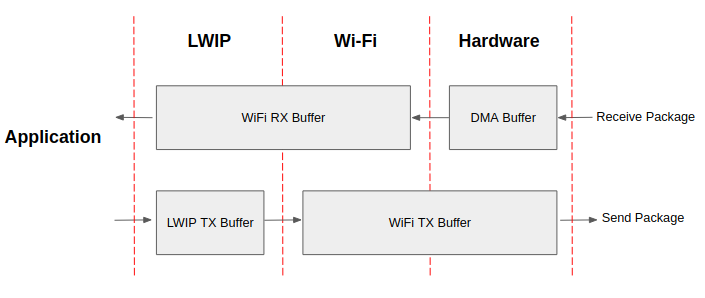
ESP32 datapath
The ESP32 protocol stack is divided into four layers: Application, LwIP, Wi-Fi,
and Hardware.
- During receiving, hardware puts the received packet into DMA buffer, and then transfers it into the RX buffer of Wi-Fi and LwIP in turn for related protocol processing, and finally to the application layer. The Wi-Fi RX buffer and the LwIP RX buffer shares the same buffer by default. In other words, the Wi-Fi forwards the packet to LwIP by reference by default.
- During sending, the application copies the messages to be sent into the TX buffer of the LwIP layer for TCP/IP encapsulation. The messages will then be passed to the TX buffer of the Wi-Fi layer for MAC encapsulation and wait to be sent.
Parameters
Increasing the size or number of the buffers mentioned above properly can
improve Wi-Fi performance. Meanwhile, it will reduce available memory to the
application. The following is an introduction to the parameters that users need
to configure:
RX direction:
- CONFIG_ESP32_WIFI_STATIC_RX_BUFFER_NUM
This parameter indicates the number of DMA buffer at the hardware
layer. Increasing this parameter will increase the sender’s one-time
receiving throughput, thereby improving the Wi-Fi protocol stack
ability to handle burst traffic.
- CONFIG_ESP32_WIFI_DYNAMIC_RX_BUFFER_NUM
This parameter indicates the number of RX buffer in the Wi-Fi layer.
Increasing this parameter will improve the performance of packet
reception. This parameter needs to match the RX buffer size of the
LwIP layer.
- CONFIG_ESP32_WIFI_RX_BA_WIN
This parameter indicates the size of the AMPDU BA Window at the
receiving end. This parameter should be configured to the smaller
value between twice of CONFIG_ESP32_WIFI_STATIC_RX_BUFFER_NUM and
CONFIG_ESP32_WIFI_DYNAMIC_RX_BUFFER_NUM.
- CONFIG_LWIP_TCP_WND_DEFAULT
This parameter represents the RX buffer size of the LwIP layer for
each TCP stream. Its value should be configured to the value of
WIFI_DYNAMIC_RX_BUFFER_NUM (KB) to reach a high and stable
performance. Meanwhile, in case of multiple streams, this value
needs to be reduced proportionally.
TX direction:
- CONFIG_ESP32_WIFI_TX_BUFFER
This parameter indicates the type of TX buffer, it is recommended to
configure it as a dynamic buffer, which can make full use of memory.
- CONFIG_ESP32_WIFI_DYNAMIC_TX_BUFFER_NUM
This parameter indicates the number of TX buffer on the Wi-Fi layer.
Increasing this parameter will improve the performance of packet sending.
The parameter value needs to match the TX buffer size of the LwIP layer.
- CONFIG_LWIP_TCP_SND_BUF_DEFAULT
This parameter represents the TX buffer size of the LwIP layer for each
TCP stream. Its value should be configured to the value of
WIFI_DYNAMIC_TX_BUFFER_NUM (KB) to reach a high and stable performance.
In case of multiple streams, this value needs to be reduced
proportionally.
Throughput optimization by placing code in IRAM:
- CONFIG_ESP32_WIFI_IRAM_OPT
If this option is enabled, some Wi-Fi functions are moved to IRAM,
improving throughput. This increases IRAM usage by 15 kB.
- CONFIG_ESP32_WIFI_RX_IRAM_OPT
If this option is enabled, some Wi-Fi RX functions are moved to IRAM,
improving throughput. This increases IRAM usage by 16 kB.
- CONFIG_LWIP_IRAM_OPTIMIZATION
If this option is enabled, some LwIP functions are moved to IRAM,
improving throughput. This increases IRAM usage by 13 kB.
Note
The buffer size mentioned above is fixed as 1.6 KB.
How to Configure Parameters
The memory of ESP32 is shared by protocol stack and applications.
Here, several configuration ranks are given. In most cases, the user should
select a suitable rank for parameter configuration according to the size of the
memory occupied by the application.
The parameters not mentioned in the following table should be set to the default.
| Rank | Iperf | TX prior
| High-performance | Default | Memory saving | Minimum
|
| Available memory (KB)
| 37.1
| 113.8
| 123.3
| 145.5
| 144.5
| 170.2
| 185.2
|
| WIFI_STATIC_RX_BUFFER_NUM
| 16
| 6
| 6
| 6
| 6
| 6
| 4
|
| WIFI_DYNAMIC_RX_BUFFER_NUM
| 64
| 16
| 24
| 34
| 20
| 12
| 8
|
| WIFI_DYNAMIC_TX_BUFFER_NUM
| 64
| 28
| 24
| 18
| 20
| 12
| 8
|
| WIFI_RX_BA_WIN
| 32
| 8
| 12
| 12
| 10
| 6
| Disable
|
| TCP_SND_BUF_DEFAULT (KB)
| 65
| 28
| 24
| 18
| 20
| 12
| 8
|
| TCP_WND_DEFAULT (KB)
| 65
| 16
| 24
| 34
| 20
| 12
| 8
|
| WIFI_IRAM_OPT
| 15
| 15
| 15
| 15
| 15
| 15
| 15
|
| WIFI_RX_IRAM_OPT
| 16
| 16
| 16
| 16
| 16
| 16
| 16
|
| LWIP_IRAM_OPTIMIZATION
| 13
| 13
| 13
| 13
| 13
| 13
| 13
|
| TCP TX throughput (Mbit/s)
| 74.6
| 50.8
| 46.5
| 39.9
| 44.2
| 33.8
| 25.6
|
| TCP RX throughput (Mbit/s)
| 63.6
| 35.5
| 42.3
| 48.5
| 40.5
| 30.1
| 27.8
|
| UDP TX throughput (Mbit/s)
| 76.2
| 75.1
| 74.1
| 72.4
| 69.6
| 64.1
| 36.5
|
| UDP RX throughput (Mbit/s)
| 83.1
| 66.3
| 75.1
| 75.6
| 73.1
| 65.3
| 54.7
|
Note
The test was performed with a single stream in a shielded box using an ASUS
RT-N66U router. ESP32’s CPU is dual core with 240 MHz. ESP32’s flash is in QIO
mode with 80 MHz.
Ranks:
- Iperf rank
ESP32 extreme performance rank used to test extreme performance.
- High-performance rank
The ESP32’s high-performance configuration rank, suitable for scenarios
where the application occupies less memory and has high-performance
requirements. In this rank, users can choose to use the RX prior rank or
the TX prior rank according to the usage scenario.
- Default rank
ESP32’s default configuration rank, the available memory, and performance
are in balance.
- Memory saving rank
This rank is suitable for scenarios where the application requires a
large amount of memory, and the transceiver performance will be reduced
in this rank.
- Minimum rank
This is the minimum configuration rank of ESP32. The protocol stack only
uses the necessary memory for running. It is suitable for scenarios
where there is no requirement for performance and the application
requires lots of space.
Using PSRAM
PSRAM is generally used when the application takes up a lot of memory. In this
mode, the CONFIG_ESP32_WIFI_TX_BUFFER is forced to be static.
CONFIG_ESP32_WIFI_STATIC_TX_BUFFER_NUM indicates the number of DMA buffers at
the hardware layer, and increasing this parameter can improve performance. The
following are the recommended ranks for using PSRAM:
| Rank | Iperf
| Default | Memory saving | Minimum
|
| Available memory (KB)
| 113.8
| 152.4
| 181.2
| 202.6
|
| WIFI_STATIC_RX_BUFFER_NUM
| 16
| 8
| 4
| 2
|
| WIFI_DYNAMIC_RX_BUFFER_NUM
| 128
| 128
| 128
| 128
|
| WIFI_STATIC_TX_BUFFER_NUM
| 16
| 8
| 4
| 2
|
| WIFI_RX_BA_WIN
| 16
| 16
| 8
| Disable
|
| TCP_SND_BUF_DEFAULT (KB)
| 65
| 65
| 65
| 65
|
| TCP_WND_DEFAULT (KB)
| 65
| 65
| 65
| 65
|
| WIFI_IRAM_OPT
| 15
| 15
| 15
| 0
|
| WIFI_RX_IRAM_OPT
| 16
| 16
| 0
| 0
|
| LWIP_IRAM_OPTIMIZATION
| 13
| 0
| 0
| 0
|
| TCP TX throughput (Mbit/s)
| 37.5
| 31.7
>21.7
| 14.6
|
| TCP RX throughput (Mbit/s)
| 31.5
| 29.8
| 26.5
| 21.1
|
| UDP TX throughput (Mbit/s)
| 69.1
| 31.5
| 27.1
| 24.1
|
| UDP RX throughput (Mbit/s)
| 40.1
| 38.5
| 37.5
| 36.9
| |
Wi-Fi Menuconfig
Wi-Fi Buffer Configure
If you are going to modify the default number or type of buffer, it would be
helpful to also have an overview of how the buffer is allocated/freed in the
data path. The following diagram shows this process in the TX direction:
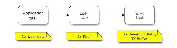 TX Buffer Allocation
Description:
TX Buffer Allocation
Description:
- The application allocates the data which needs to be sent out.
- The application calls TCPIP-/Socket-related APIs to send the user data.
These APIs will allocate a PBUF used in LwIP, and make a copy of the user data.
- When LwIP calls a Wi-Fi API to send the PBUF, the Wi-Fi API will allocate a
“Dynamic Tx Buffer” or “Static Tx Buffer”, make a copy of the LwIP PBUF, and f
inally send the data.
The following diagram shows how buffer is allocated/freed in the RX direction:
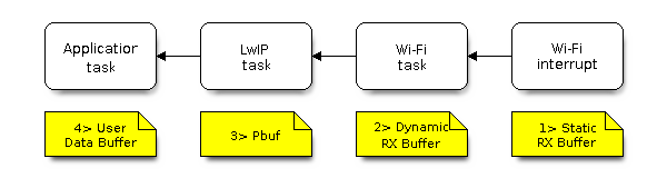 RX Buffer Allocation
Description:
RX Buffer Allocation
Description:
- The Wi-Fi hardware receives a packet over the air and puts the packet content to the “Static Rx Buffer”, which is also called “RX DMA Buffer”.
- The Wi-Fi driver allocates a “Dynamic Rx Buffer”, makes a copy of the “Static Rx Buffer”, and returns the “Static Rx Buffer” to hardware.
- The Wi-Fi driver delivers the packet to the upper-layer (LwIP), and allocates a PBUF for holding the “Dynamic Rx Buffer”.
- The application receives data from LwIP.
The diagram shows the configuration of the Wi-Fi internal buffer.
| Buffer Type | Alloc Type | Default
| Configurable | Description
|
| Static RX Buffer (Hardware RX Buffer)
| Static
| 10 * 1600 Bytes
| Yes
| This is a kind of DMA memory. It is initialized in esp_wifi_init() and freed
in esp_wifi_deinit(). The ‘Static Rx Buffer’ forms the hardware receiving list.
Upon receiving a frame over the air, hardware writes the frame into the buffer
and raises an interrupt to the CPU. Then, the Wi-Fi driver reads the content
from the buffer and returns the buffer back to the list.
If needs be, the application can reduce the memory statically allocated by
Wi-Fi. It can reduce this value from 10 to 6 to save 6400 Bytes of memory. It is
not recommended to reduce the configuration to a value less than 6 unless the
AMPDU feature is disabled.
|
| Dynamic RX Buffer
| Dynamic
| 32
| Yes
| The buffer length is variable and it depends on the received frames’ length.
When the Wi-Fi driver receives a frame from the ‘Hardware Rx Buffer’, the
‘Dynamic Rx Buffer’ needs to be allocated from the heap. The number of the
Dynamic Rx Buffer, configured in the menuconfig, is used to limit the total
un-freed Dynamic Rx Buffer number.
|
| Dynamic TX Buffer
| Dynamic
| 32
| Yes
| This is a kind of DMA memory. It is allocated to the heap. When the
upper-layer (LwIP) sends packets to the Wi-Fi driver, it firstly allocates a
‘Dynamic TX Buffer’ and makes a copy of the upper-layer buffer.
The Dynamic and Static TX Buffers are mutually exclusive.
|
| Static TX Buffer
| Static
| 16 * 1600Bytes
| Yes
| This is a kind of DMA memory. It is initialized in esp_wifi_init() and freed
in esp_wifi_deinit(). When the upper-layer (LwIP) sends packets to the Wi-Fi
driver, it firstly allocates a ‘Static TX Buffer’ and makes a copy of the
upper-layer buffer.
The Dynamic and Static TX Buffer are mutually exclusive.
The TX buffer must be a DMA buffer. For this reason, if PSRAM is enabled, the
TX buffer must be static.
|
| Management Short Buffer
| Dynamic
| 8
| NO
| Wi-Fi driver’s internal buffer.
|
| Management Long Buffer
| Dynamic
| 32
| NO
|
Wi-Fi driver’s internal buffer.
|
| Management Long Long Buffer
| Dynamic
| 32
| NO
| Wi-Fi driver’s internal buffer.
|
Wi-Fi NVS Flash
If the Wi-Fi NVS flash is enabled, all Wi-Fi configurations set via the Wi-Fi
APIs will be stored into flash, and the Wi-Fi driver will start up with these
configurations the next time it powers on/reboots. However, the application can
choose to disable the Wi-Fi NVS flash if it does not need to store the
configurations into persistent memory, or has its own persistent storage, or
simply due to debugging reasons, etc.
Wi-Fi Aggregate MAC Protocol Data Unit (AMPDU)
ESP32 supports both receiving and transmitting AMPDU, and the AMPDU can greatly
improve the Wi-Fi throughput.
Generally, the AMPDU should be enabled. Disabling AMPDU is usually for debugging
purposes.
Troubleshooting
Please refer to a separate document with Espressif Wireshark User Guide.