How I2C Communication Works? Arduino and I2C Tutorial
Photo of author
by Dejan
Arduino Tutorials
In this tutorial we will learn how the I2C communication protocol works and also
we will make a practical example of it with the Arduino Board and a sensor which
uses this protocol. You can watch the following video or read the written
tutorial below.
Overview
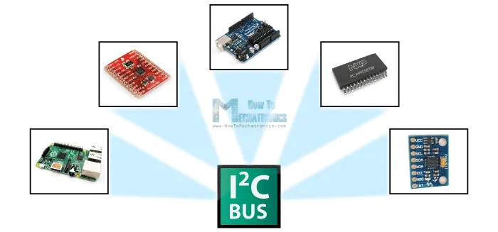
The I2C communication bus is very popular and broadly used by many electronic
devices because it can be easily implemented in many electronic designs which
require communication between a master and multiple slave devices or even
multiple master devices. The easy implementations comes with the fact that only
two wires are required for communication between up to almost 128 (112) devices
when using 7 bits addressing and up to almost 1024 (1008) devices when using 10
bits addressing.
 I2C-Communication-Overview1
How I2C Works
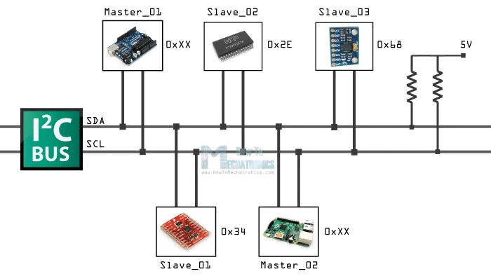
How is it possible, a communication between so many devices with just to wires?
Well each device has a preset ID or a unique device address so the master can
choose with which devices will be communicating.
The two wires, or lines are called Serial Clock (or SCL) and Serial Data (or
SDA). The SCL line is the clock signal which synchronize the data transfer
between the devices on the I2C bus and it’s generated by the master device. The
other line is the SDA line which carries the data.
The two lines are “open-drain” which means that pull up resistors needs to be
attached to them so that the lines are high because the devices on the I2C bus
are active low. Commonly used values for the resistors are from 2K for higher
speeds at about 400 kbps, to 10K for lower speed at about 100 kbps.
I2C-Communication--How-It-Works
I2C Protocol
 I2C-Communcation-Protocol
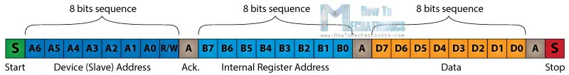
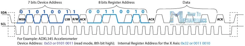
The data signal is transferred in sequences of 8 bits. So after a special start
condition occurs comes the first 8 bits sequence which indicates the address of
the slave to which the data is being sent. After each 8 bits sequence follows a
bit called Acknowledge. After the first Acknowledge bit in most cases comes
another addressing sequence but this time for the internal registers of the
slave device. Right after the addressing sequences follows the data sequences as
many until the data is completely sent and it ends with a special stop condition.
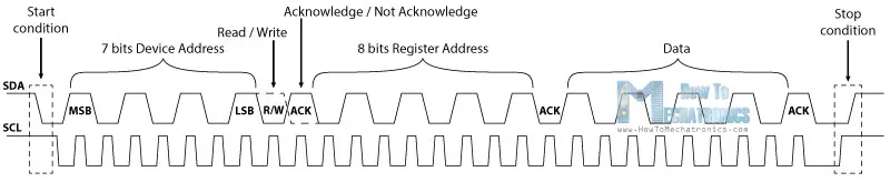
Let’s take even closer look at these events. The start condition occurs when
data line drops low while the clock line is still high. After this the clock
starts and each data bit is transferred during each clock pulse.
The device addressing sequence stars with the most significant bit (MSB) first
and ends with the least significant bit (LSB) and it’s actually composed of 7
bits because the 8th bit is used for indicating whether the master will write to
the slave (logic low) or read from it (logic high).
I2C-Communcation-Protocol
The data signal is transferred in sequences of 8 bits. So after a special start
condition occurs comes the first 8 bits sequence which indicates the address of
the slave to which the data is being sent. After each 8 bits sequence follows a
bit called Acknowledge. After the first Acknowledge bit in most cases comes
another addressing sequence but this time for the internal registers of the
slave device. Right after the addressing sequences follows the data sequences as
many until the data is completely sent and it ends with a special stop condition.
Let’s take even closer look at these events. The start condition occurs when
data line drops low while the clock line is still high. After this the clock
starts and each data bit is transferred during each clock pulse.
The device addressing sequence stars with the most significant bit (MSB) first
and ends with the least significant bit (LSB) and it’s actually composed of 7
bits because the 8th bit is used for indicating whether the master will write to
the slave (logic low) or read from it (logic high).
 I2C-Bits-Protocol
The next bit AKC/ NACK is used by the slave device to indicate whether it has
successfully received the previous sequence of bits. So at this time the master
device hands the control of the SDA line over to the slave device and if the
slave device has successfully received the previous sequence it will pull the
SDA line down to the condition called Acknowledge. If the slave does not pull
the SDA line down, the condition is called Not Acknowledge, and means that it
didn’t successfully received the previous sequence which can be caused by
several reasons. For example, the slave might be busy, might not understand the
received data or command, cannot receive any more data and so on. In such a
case the master device decides how it will proceed.
I2C-Bits-Protocol
The next bit AKC/ NACK is used by the slave device to indicate whether it has
successfully received the previous sequence of bits. So at this time the master
device hands the control of the SDA line over to the slave device and if the
slave device has successfully received the previous sequence it will pull the
SDA line down to the condition called Acknowledge. If the slave does not pull
the SDA line down, the condition is called Not Acknowledge, and means that it
didn’t successfully received the previous sequence which can be caused by
several reasons. For example, the slave might be busy, might not understand the
received data or command, cannot receive any more data and so on. In such a
case the master device decides how it will proceed.
 I2C-Bits-Protocol_ADXL-X-Axis-Example
Next is the internal registers addressing. The internal registers are locations
in the slave’s memory containing various information or data. For example the
ADX345 Accelerometer has a unique device address and addition internal registers
addresses for the X, Y and Z axis. So if we want to read the data of the X-axis,
first we need to send the device address and then the particular internal
register address for the X-axis. These addresses can be found from datasheet of
the sensor.
After the addressing, the data transfer sequences begin either from the master
or the slave depending of the selected mode at the R/W bit. After the data is
completely sent, the transfer will end with a stop condition which occurs when
the SDA line goes from low to high while the SCL line is high.
I2C-Bits-Protocol_ADXL-X-Axis-Example
Next is the internal registers addressing. The internal registers are locations
in the slave’s memory containing various information or data. For example the
ADX345 Accelerometer has a unique device address and addition internal registers
addresses for the X, Y and Z axis. So if we want to read the data of the X-axis,
first we need to send the device address and then the particular internal
register address for the X-axis. These addresses can be found from datasheet of
the sensor.
After the addressing, the data transfer sequences begin either from the master
or the slave depending of the selected mode at the R/W bit. After the data is
completely sent, the transfer will end with a stop condition which occurs when
the SDA line goes from low to high while the SCL line is high.
Example
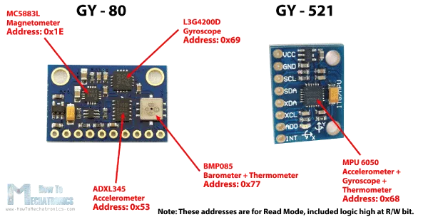
As an example I will use the GY-80 breakout board which consists 5 different
sensors and the GY-521 breakout board which consists 3 different sensors. So we
can get data from 8 different sensors with just two wires with the I2C bus.
 GY---80-and-GY---521-Addresses
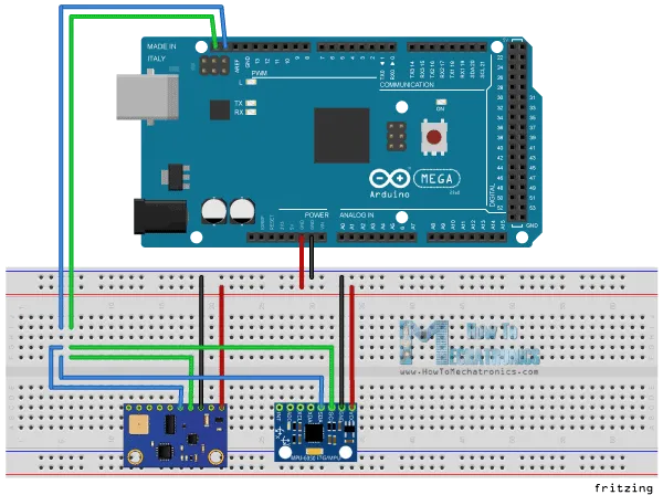
Here’s how we will connect the boards. The Serial Clock pin of the Arduino Board
will be connected to the Serial Clock pins of the two breakout boards, the same
goes for the Serial Data pins and we will power the boards with the Gnd and the
5V pin from the Arduino Board. Note here we are not using pull-up resistors
because the breakout boards already have.
GY---80-and-GY---521-Addresses
Here’s how we will connect the boards. The Serial Clock pin of the Arduino Board
will be connected to the Serial Clock pins of the two breakout boards, the same
goes for the Serial Data pins and we will power the boards with the Gnd and the
5V pin from the Arduino Board. Note here we are not using pull-up resistors
because the breakout boards already have.
 I2C-and-Arduino-Circuit-Schematics
Now in order to communicate with these chips or sensors we need to know their
unique addresses. We can find them from the datasheets of the sensors. For the
GY-80 breakout board we have the following 4 addresses: a hexadecimal 0x53 for
the 3 Axis Accelerometer sensor, a hexadecimal 0x69 for the 3 Axis Gyro, a
hexadecimal 0x1E for the 3 Axis Magnetometer and a hexadecimal 0x77 for the
Barometer and Thermometer sensor.
See Also
Arduino and MPU6050 Accelerometer and Gyroscope Tutorial
For the GY-521 breakout board we have only one address and that’s a hexadecimal
0x68. We can also get or check the addresses using the Arduino I2C Scanner
sketch which can be found from the Arduino official website. So here if we
upload and run that sketch, we will get the addresses of the connected devices
on the I2C bus.
I2C-and-Arduino-Circuit-Schematics
Now in order to communicate with these chips or sensors we need to know their
unique addresses. We can find them from the datasheets of the sensors. For the
GY-80 breakout board we have the following 4 addresses: a hexadecimal 0x53 for
the 3 Axis Accelerometer sensor, a hexadecimal 0x69 for the 3 Axis Gyro, a
hexadecimal 0x1E for the 3 Axis Magnetometer and a hexadecimal 0x77 for the
Barometer and Thermometer sensor.
See Also
Arduino and MPU6050 Accelerometer and Gyroscope Tutorial
For the GY-521 breakout board we have only one address and that’s a hexadecimal
0x68. We can also get or check the addresses using the Arduino I2C Scanner
sketch which can be found from the Arduino official website. So here if we
upload and run that sketch, we will get the addresses of the connected devices
on the I2C bus.
 Sensor Part Number I2C Address
3 Axis Accelerometer Analog Devices ADXL345 0x53 Datasheet
3 Axis GyroST Microelectronics L3G4200D 0x69 Datasheet
3 Axis Magnetometer Honeywell MC5883L 0x1E Datasheet
Barometer + Thermometer Bosch BMP085 0x77 Datasheet
After we have found the addresses of the devices we also need to find the
addresses of their internal registers in order to read the data from them. For
example if we want to read the data for the X axis from the 3 Axis Accelerometer
sensor of the GY-80 breakout board, we need to find the internal register
address where the data of the X axis is stored. From the datasheet of the sensor
, we can see that data for the X axis is actually stored in two registers,
DATAX0 with a hexadecimal address 0x32 and DATAX1 with a hexadecimal address 0x33.
Sensor Part Number I2C Address
3 Axis Accelerometer Analog Devices ADXL345 0x53 Datasheet
3 Axis GyroST Microelectronics L3G4200D 0x69 Datasheet
3 Axis Magnetometer Honeywell MC5883L 0x1E Datasheet
Barometer + Thermometer Bosch BMP085 0x77 Datasheet
After we have found the addresses of the devices we also need to find the
addresses of their internal registers in order to read the data from them. For
example if we want to read the data for the X axis from the 3 Axis Accelerometer
sensor of the GY-80 breakout board, we need to find the internal register
address where the data of the X axis is stored. From the datasheet of the sensor
, we can see that data for the X axis is actually stored in two registers,
DATAX0 with a hexadecimal address 0x32 and DATAX1 with a hexadecimal address 0x33.
Arduino I2C Code
Now let’s make the code that will get the data for the X axis. So we will use
the Arduino Wire Library which has to be include in the sketch. Here first we
have to define the sensor address and the two internal registers addresses that
we previously found. The Wire.begin() function will initiate the Wire library
and also we need to initiate the serial communication because we will use the
Serial Monitor to show the data from the sensor.
In the loop() we will start with the Wire.beginTransmission() function which
will begin the transmission to the particular sensor, the 3 Axis Accelerometer
in our case. Then with the Wire.write() function we will ask for the particular
data from the two registers of the X axis. The Wire.endTransmission() will end
the transmission and transmit the data from the registers. Now with the
Wire.requestFrom() function we will request the transmitted data or the two
bytes from the two registers.
The Wire.available() function will return the number of bytes available for
retrieval and if that number match with our requested bytes, in our case 2 bytes
, using the Wire.read() function we will read the bytes from the two registers
of the X axis. At the end we will print the data into the serial monitor. Here’s
that data but keep in mind that this is raw data and some math is needed to be
done in order to get the right values of the X axis. You can find more details
for that in my next tutorial for using accelerometers with the Arduino Board
because I don’t want to overload this tutorial because its main goal was to
explain how the Arduino I2C communication works.
/*H*******************************************************
* How I2C Communication Protocol Works - Arduino I2C Tutorial
* by Dejan, www.HowToMechatronics.com
********************************************************/
#include <Wire.h>
//************************* DEFINES ************************************
#define X_Axis_Register_DATAX0 0x32 // Hex addr DATAX0 internal register
#define X_Axis_Register_DATAX1 0x33 // Hex add for DATAX1 internal register
#define Power_Register 0x2D // Power Control Register
//************************* PROTOTYPES ************************************
//************************* VARIABLES ************************************
int ADXLAddress = 0x53; // Dev addr also with 8th bit for mode, read
int X0, X1, X_out;
/*F********************************************************************
*
**********************************************************************/
void
setup()
{
Wire.begin(); // Initiate the Wire library
Serial.begin( BAUD );
delay( 100 );
Wire.beginTransmission( ADXLAddress ); // Enable measurement
Wire.write( Power_Register );
Wire.write( 8 ); // Bit D3 High for measuring enable (0000 1000)
Wire.endTransmission();
}
/*F********************************************************************
*
**********************************************************************/
void
loop()
{
Wire.beginTransmission( ADXLAddress ); // BEGIN TRANSMISSION TO SENSOR
Wire.write( X_Axis_Register_DATAX0 );//ASK PARTICULAR REGISTERS FOR DATA
Wire.write( X_Axis_Register_DATAX1 );
Wire.endTransmission(); // ENDS TRANSMISSION AND TRANSMITS DATA FROM TWO REGISTERS
Wire.requestFrom( ADXLAddress,2 ); // REQUEST TRANSMITTED TWO BYTES FROM TWO REGISTERS
if( Wire.available() <= 2 )
{ //
X0 = Wire.read(); // READS DATA FROM REGISTER
X1 = Wire.read();
}
Serial.print( "X0= " );
Serial.print( X0 );
Serial.print( " X1= " );
Serial.println( X1 );
}